PCSR |
| Main Project Aim: Convert original 3D-Printed design by Aeromech into a mahinable one.
Secondary Project Aim: + Maintain all the original features. + Omni-directional catch + Alternate "Spring Guide" design for floating plunger head + Ease of disassembly + NO INTERNAL CUTS. If you have any question you can contact me through: captainslg@aol.com |
Construction |
|
Essential Tools + Band Saw or Scroll Saw + Drillpress or Power Drill + 9/16" & 5/8" size flat-blade wood-boring drill bits + Mitre Box & Mitre Saw + #6-32 Tapping Bit + Fine-Point Permanent Marker + Tri-point ruler + Screwdriver + Half-Round Rasp + 300 grit sandpaper + Hobby Knife (to clean the edges of the sheets once cut) + Scissors + Inkjet or Laser printer + Packet of full-sheet label paper + Electrical tape + Face Shield or Safety glasses + Super Glue + PVC Cement + Silicone Grease + Vice or C-Clamp No other tools expressly needed. All tools listed are not easily substitutable. You can cut out the center of one part using a Scroll Saw or Coping Saw, and a Band Saw could be used to make the external cuts more quickly. Part List Download: pcsr_partlist.xls All items available through http://www.mcmaster.com A full set of prices is included. Simply copy and paste the first two columns into the text box of the McMaster Carr "Build Order" page. |
Step One |
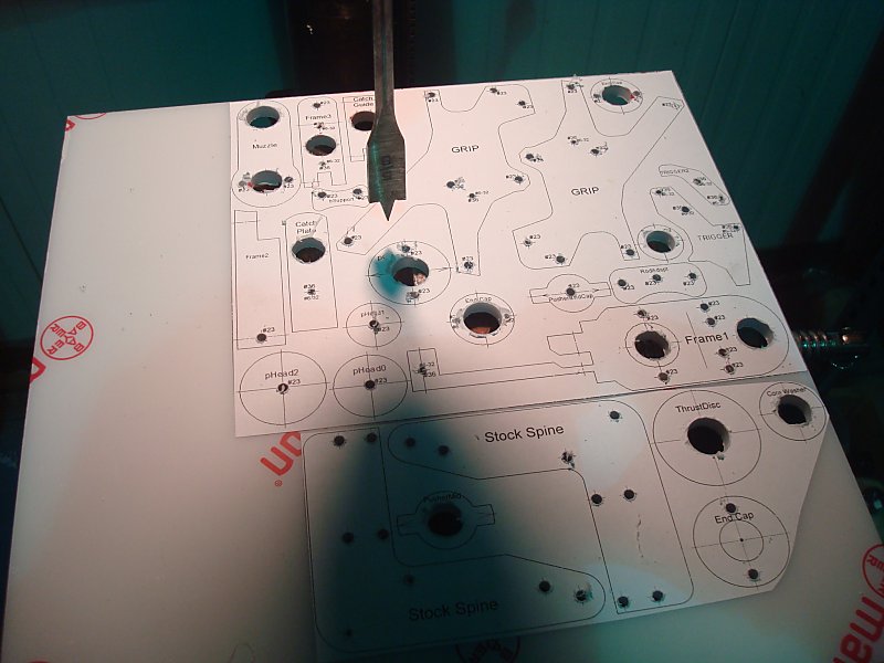
| Download the cutting template sheets: pcsr_templates.doc Print them on full sheet label paper. The included legend will tell you what size holes need to be drilled where. Most of which are labeled with the bit size or tapping requirements. Any unspecified holes should be drilled for clearance of a #6-32 screw (typically a #23 or 5/32). Using a Hammer and a Center Punch (or a Nail) put a centering divot on the centermark of every hole on every part template. |
Step Two |
|
Using a Drill Press drill all of the holes labeled as "#6-32" with a #36 or 7/64" drill bit.
Then drill all the unlabeled holes with a #23 or 5/32" drill bit. |
Step Three |
|
Using a Drill Press and a 9/16" Flat Wood-boring drill bit bore out all the holes labeled "9/16". Go slowly and carefully with minimal downforce to help avoid tearing the templates off the plastic.
Using a Drill Press and a 5/8" Flat Wood-boring drill bit bore out all the holes labeled "5/8". Go slowly and carefully with minimal downforce to help avoid tearing the templates off the plastic. |
Step Four |
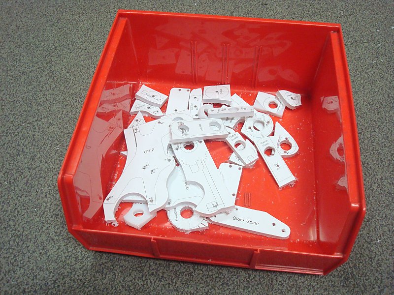
| Using a Scroll Saw or a Band Saw coarsely cut all of the parts free from the plastic sheet. |
Step Five |
|
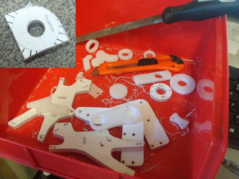
Add as many relief cuts as you think are needed. A relief cut is a cut made perpendicular to the intended cutting line that allows excess material to break away as the cut is made along the intended contour.
Using a Scroll Saw or a Band Saw accurately cut all of the parts to their outlines. Using a Hobby Knife deburr all the cut edges of the now mostly-finished pieces. Use a #6-32 Tapping Bit and Tapping Wrench to add a thread to all of the #36 holes. |
Step Six |
|
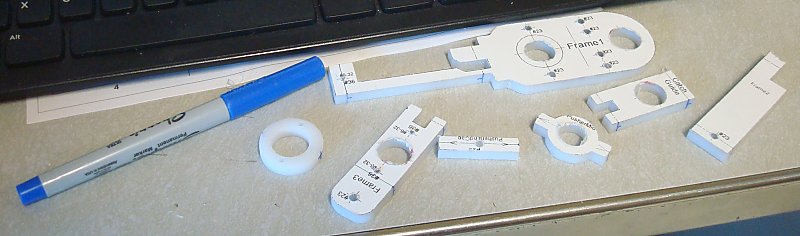
Using a Fine-Point Permanent Marker draw a line on the edges of the now cut parts whereever a dotted line meets the edge of the template.
Also mark a perpendicular line as close to the approximate center point of the edge of the piece. Using a Vice and a Drill Press drill all of these new center marks with a a #36 or 7/64" drill bit. Using your #6-32 tapping bit and a Tapping Wrench tap all of the holes you previously drilled with a #36 or 7/64" drill bit. If needed, lubricate your tapping bit with common dish soap. |
Step Seven |
|
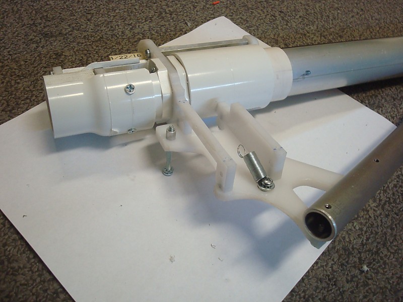
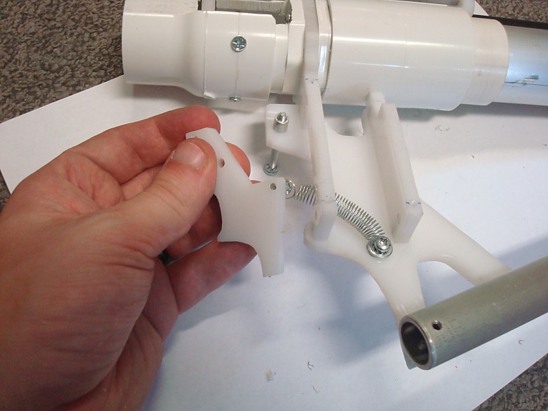
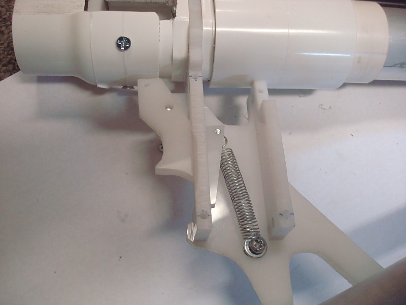
Assemble the stock components as shown. The left Stock plate should be attached to the edges of Frame3 and Catch Guide using 1/2" length screws. The extension spring should link the catch plate to the inside of the left Stock plate.
The 1-1/2" length screw is screw into the left Stock Plate, which is the one that has two tapped holes in it. The Trigger2 piece should have 1/4" length spacers on both sie of it when slide onto the 1-1/2" length screw. |
Step Eight |
|
Cut a 4-1/4" Length of 1-1/4 Schedule 40 pipe.
Cut out the Pump Grip template and wrap it around the pipe. Tape it on so that it doesn't shift around. Use a Center Punch and a hammer to mark the center of all four holes. Use a Drill Press and a #23 Drill Bit to drill all four holes. Deburr and sand all the edges of this part. Optionally you can cut rings of 1-1/2 SCH40 pipe of 1-1/4 fittings and PVC cement them to its ends to add flanges for extra grip. |
Step Nine |
| Assemble the Barrel Holder as shown using 3/4" length screws. |
Step Ten |
|
Finish the Stock assembly by adding the right side Stock Plate. Then attach the assembly to the lower stock rod.
Dimensions for the lower stock rod are included in the template set. |
Step Eleven |
|
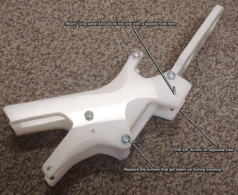
Do a test assembly of the Grip. The RIGHT Grip panel should be the one with two #6-32 tapped holes in it.
Sand all of the edges until it's comfortable enough for you to hold tightly. |
Step Twelve |
|
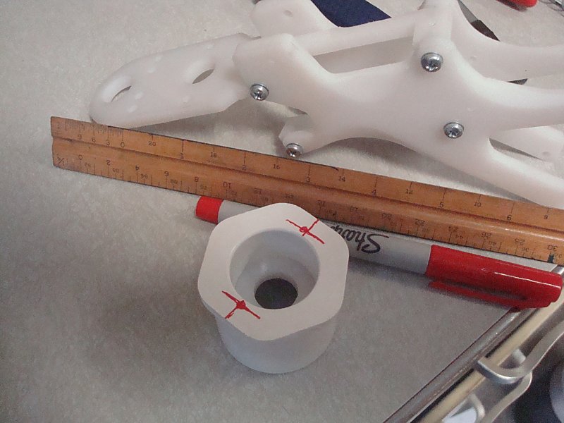
Sand the face of the 1-1/4 x 3/4 Bushing Adapter until it's flat. These typically include raised lettering that we want to get rid of.
Sand the Core Washer piece into it fits snugly into the 1-1/4 x 3/4 Bushing adapter. Using the grip assembly as a template, mark where the holes need to be drilled. Use a ruler to double check these marks relative to the centerline of the bushing. Use a hammer and a center punch to mark the center for these holes. |
Step Thirteen |
|
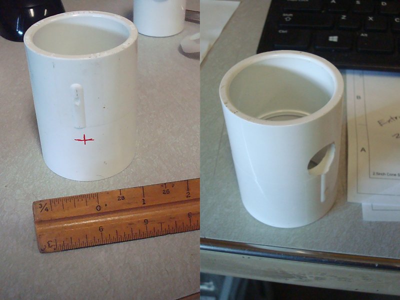
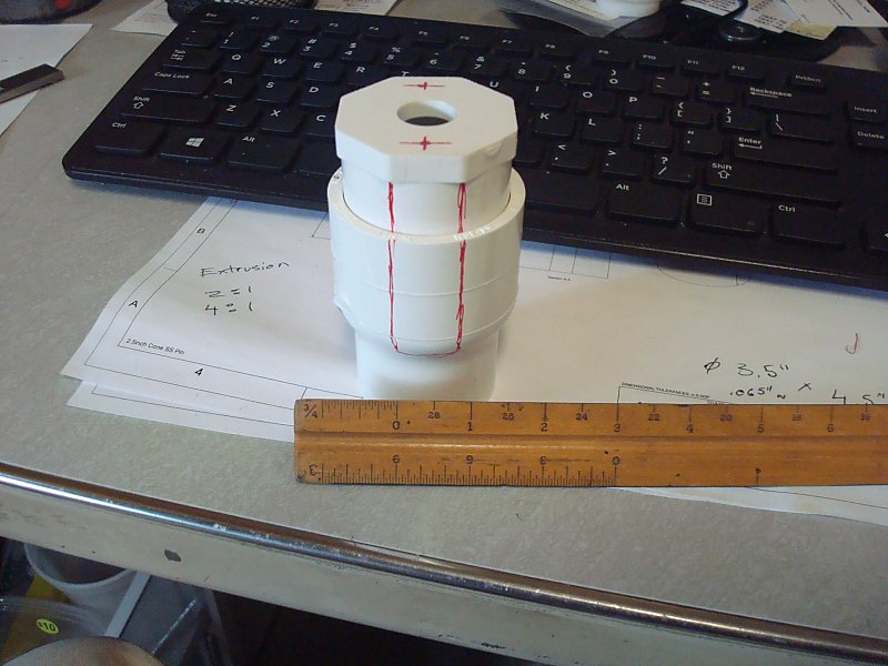
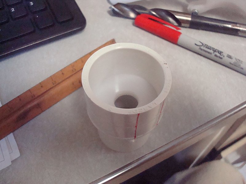
Use a tri-sided ruler to mark a spot 1-inch away from one end of the 1-1/4 coupler.
Use a hammer and a center punch to mark the center for this hole. Use a Vice, Drill Press, and 5/8" wood-boring drill bit to drill this hole. |
Step Fourteen |
|
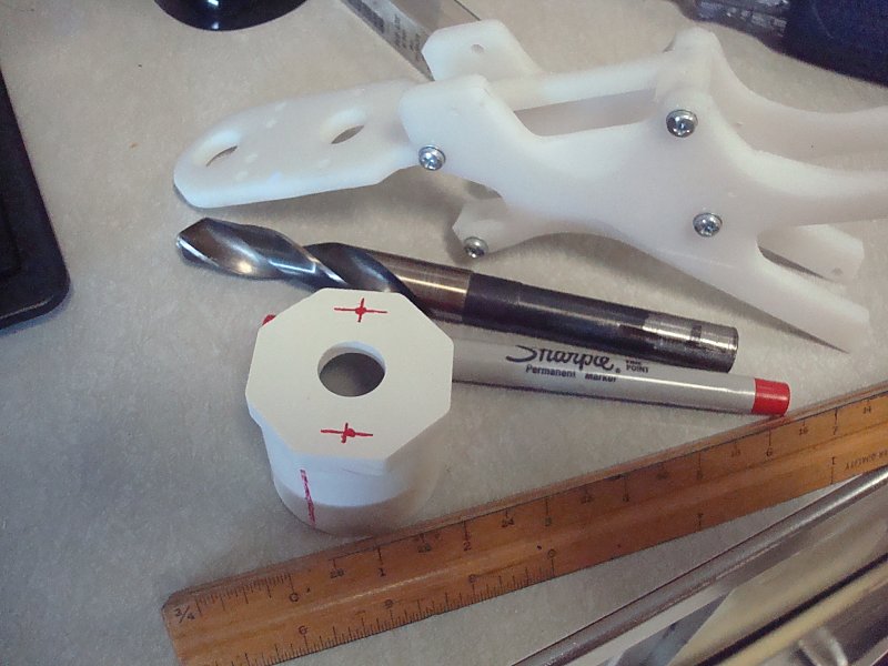
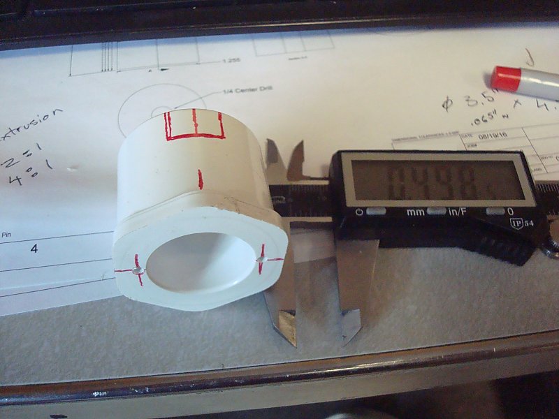
Sand the face of the 1-1/4 Plug until it's flat. These typically include raised lettering that we want to get rid of.
Use a Tri-sided ruler to find the exact center of the 1-1/4 Plug, then mark it with a fine-point permanent marker. Use a center punch and a hammer to mark the center for this hole. Use a Drill Press and a 5/8" wood-boring drill bit to put a hole in the center of the 1-1/4 Plug Using the grip assembly as a template, mark where the holes need to be drilled in the 1-1/4 Plug. Use a ruler to double check these marks relative to the centerline of the bushing. Use a hammer and a center punch to mark the center for these holes. Use a Drill Press and a #23 drill bit to drill these two holes. |
Step Fifteen |
| Use a tri-sided ruler to mark lines on both sides of the 1-1/4 Plug and the Reducing Coupler similar to shown relative to the flats on the Plug. |
Step Sixteen |
| Sand the THRUST DISC until it fits snugly into the wider end of the Reducing Coupler. |
Step Seventeen |
|
Use a Caliper or Tri-sided Ruler to mark a 3/4 x 3/4 square into the back side and center of the 1-1/4 x 3/4 Bushing.
Use a Scroll Saw, Band Saw, or a Square File to remove all of the material from this one side of the Bushing. This cutout is clearance for the CPVC stub that will be added to the coupler later. Using a Drill Press drill the two center marks made earlier using a #36 drill bit. Drill them 3/4" to 1" deep. Use a #6-32 tapping bit and tapping wrench to add a thread to these holes. |
Step Eighteen |
| Use a Scroll Saw or a Band Saw to cut the marker slots out of both the Reducing Coupler and the 1-1/4 Plug. |
Step Nineteen |
|
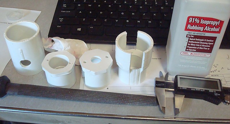
Test the assembly of the Reducing Coupler, THRUST DISC, and 1-1/4 Plug.
Us a half-round rasp to clean all of the cut edges as well as flatten out the backside of the #23 holes that were drilled in the 1-1/4 Plug. |
Step Twenty |
|
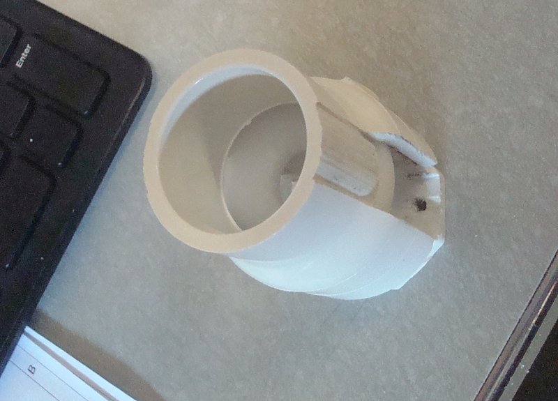
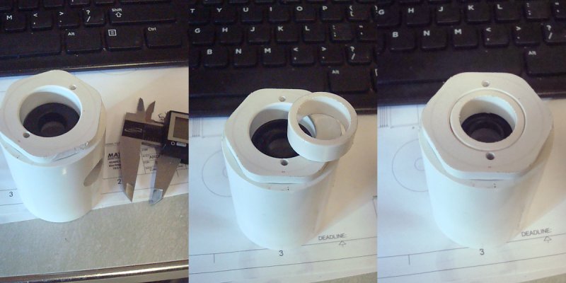
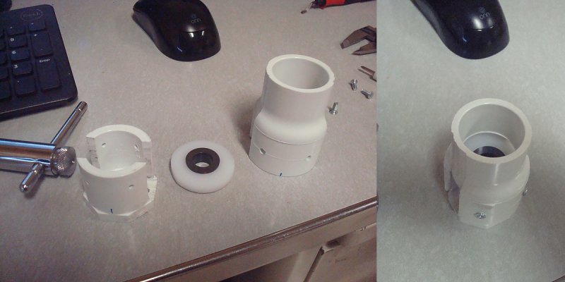
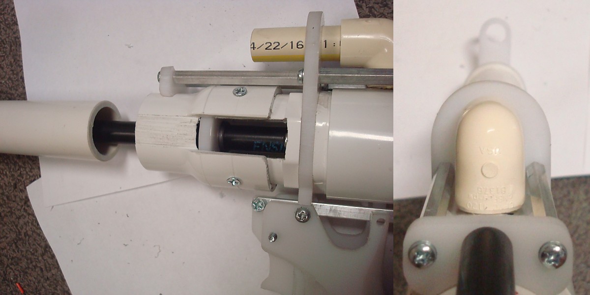
Precisely align the bushing relative to the 1-1/4 Coupler so that the two threaded holes are perpendicular with the 5/8" hole drilled into the side of the coupler.
Press the Bushing into the end of the coupler that's closest to the hole drilled in the side. Slip the Core Washer into the Bushing. Slip the U-Cup seal into the Bushing. The orientation shown in the far left of the image is CORRECT. The orientation shown in the middle and right panels is INCORRECT and will not seal correctly. The U-Cup is slightly orientation sensitive. The left panel in Step Twenty is the orientation that's most likely to be reliable since the pressure of the plunger cycling will help expand the u-cup to seal better. It or the priming rod will need to be lubricated a little bit and you may have to dry fire several times before it works optimally. Measure the depth from the face of the Bushing to the back of the U-Cup washer. Use a Ratcheting Pipe Cutter or Band Saw to cut a piece of 3/4 pipe that's just slightly longer than the depth you just measured. The ends of this piece need to be very square so sanding them is likely to be needed. |
Step Twenty One |
|
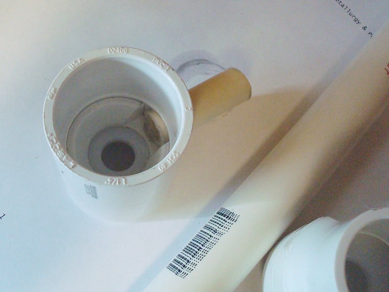
Set aside the u-cup washer and 3/4 pipe section for later.
cut a 2-inch or longer piece of 1/2 CTS CPVC and use PVC cement to glue it into the 5/8" hole drilled into the side of the Coupler. This stub should clear the notch cut into the bushing earlier. |
Step Twenty Two |
|
Using the mold seam on the Reducing Coupler as a guide, mark 4 centers at even spacings.
Use a Vice, Drill Press, and a #23 drill bit to drill out these holes. Insert the THRUST DISC into the wider side of the Reducing Coupler Slide the Reducing Coupler onto the 1-1/4 Plug and align the slots. Use the previously drilled holes to mark the 1-1/4 Plug with a fine-point permanent marker. |
Step Twenty Three |
|
Use a Vice, Drill Press, and a #36 drill bit to drill out these holes in the 1-1/4 Plug.
Using a #6-32 tapping bit and a Tapping Wrench tap these four holes. Press the flanged sleeve bearing into the center hole of the THRUST DISC. Use 3/8" length screws to assemble all of the parts as shown. |
Step Twenty Four |
|
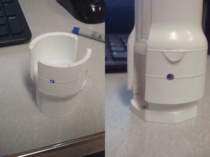
Use Two 3/4" length screws to test-assemble the grip with the prior two assemblies.
Check alignment between the 5/8" hole in the top of the grip assembly and the 1/2 CTS CPVC stub that's sticking out of the coupler. You may need to remove the Bushing from the Coupler and adjust their relative alignment. |
Step Twenty Five |
|
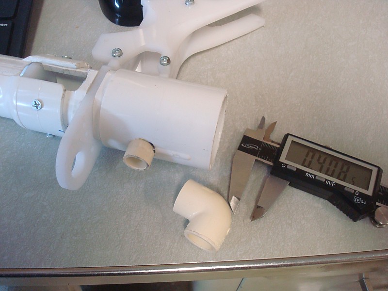
Sand down one leg of a 1/2 CTS CPVC Elbow until the slip connection is only 3/8" deep.
Using a Ratcheting Pipe Cutter or a Band Saw cut the 1/2 CTS CPVC stub sticking out of the coupler down to .406" maximum length from the coupler. Sand and deburr the edges of both parts. Test-fit the coupler onto the stub so that the leg of the Elbow that you didn't cut lines up with the 5/8" hole in the top of FRAME1 |
Step Twenty Six |
|
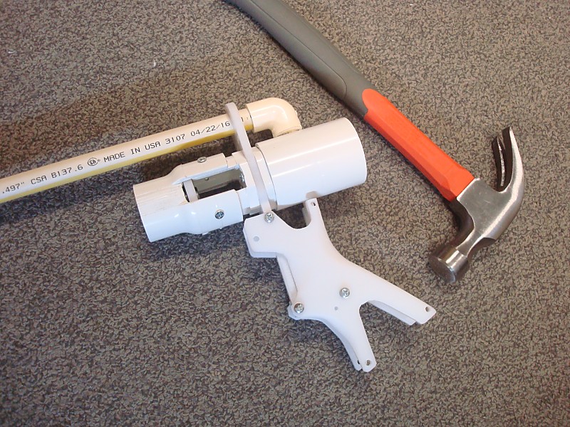
Confirm alignment of the elbow with a long piece of 1/2 CTS CPVC.
Make any adjustments to these parts as needed until things line up well and the long piece of 1/2 CPVC is parallel with the assembly. Once everything is aligned use PVC Cement to adhere the Elbow to the stub sticking out of the Coupler. Use the long piece of 1/2 CPVC to fixture and align it while it cures. YOU ARE ONLY ADHERING THE ELBOW TO THE STUB ON THE COUPLER. You DO NOT need to adhere the longer stud into the elbow. Being able to remove the stub later allows the entire plunger tube assembly to be removable from the blaster. |
Step Twenty Seven |
|
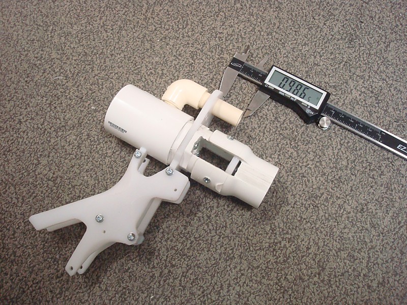
After the PVC Cement has finished curing, mark the long piece of 1/2 CTS CPVC a minimum of .986" away from FRAME1 then remove it from the elbow and cut it where marked.
Deburr and sand the edges of the shortened stub. Then Resinstall it as shown. |
Step Twenty Eight |
|
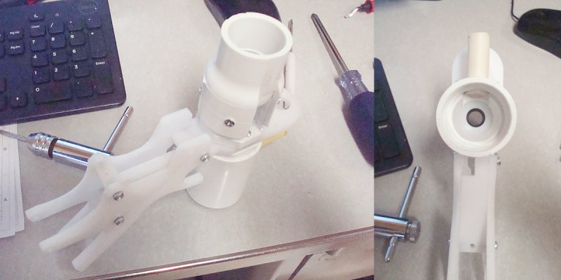
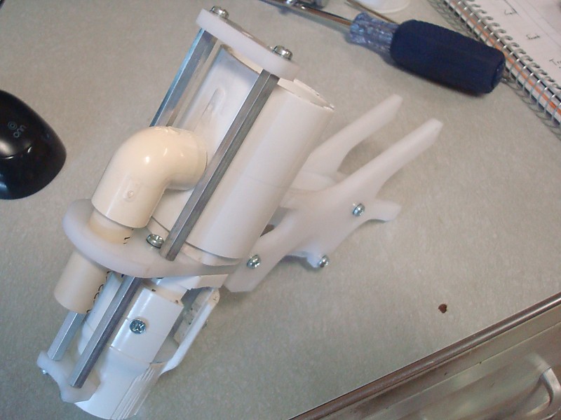
Use Eight 1/2" length screws to attach the aluminum spacers, bSupport, and RodAdapt components to the grip assembly.
The longer spacers and the RodAdapt part install on the rear of the assembly. The shorter spacers and the bSupport pieces go on the front. |
Step Twenty Nine |
|
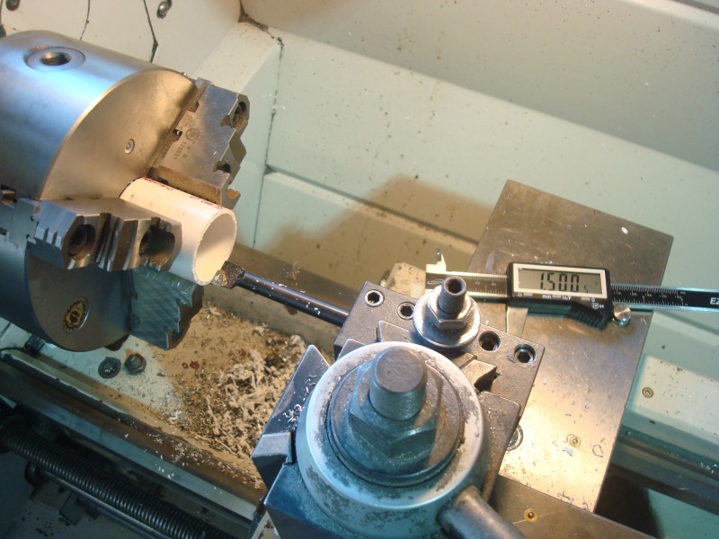
This specific part is optional if you are intending to use a plunger tube that isn't 1-1/4 Schedule 40 Pipe.
Cut a 2 inch long piece of 1-1/4 SCH40 pipe then use a boring bar on a lathe to cut the ID to 1.505" FOR THIS AND ALL OTHER PLUNGER TUBE SIZES: Cut your prefered plunger tube to 10-5/8" in length. |
Step Thirty |
|
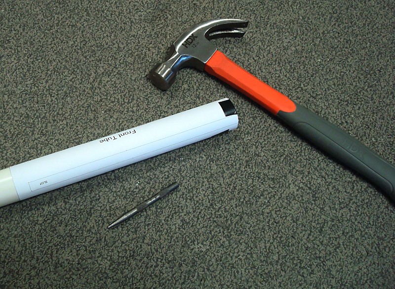
Cut a 1-foot length of 1 NPS Schedule 40 pipe.
Cut out and wrap the Front Tube template around one end of the Front Tube. Tape it in place so that it cannot shift around. Use a center punch and a hammer to mark the center of both holes. Also use it to mark the corners for the slots, and the mid-point of the lines for the slots. |
Step Thirty One |
|
Remove the paper template and use a fine-point permanent marker to highlight the center marks you just made.
Use a tri-sided ruler to connect the center marks for the midpoint of the clot cuts and the corner marks. Extend this line to the fron end of the Front Tube. Then connect the corner marks. Use a Drill Press and a #23 drill bit to drill the two holes. Use a Scroll Saw, Band Saw, or Jig Saw to cut the slots as marked. Use a Half-Round Rasp to clean of the cut edges. Deburr any remaining edges. |
Step Thirty Two |
|
Cut a 3: length piece of 1 NPS Schedule 40 pipe.
Cut out the WIFFLE TUBE template and wrap it around the pipe. Tape it in place so that it cannot shift around. Use a center punch and a hammer to mark the center of all of the holes. Use a Vice, Drill Press, and a 1/2" Wood-Boring Drill Bit to drill all of the holes. |
Step Thirty Three |
|
Use Super Glue to adhere the WIFFLE TUBE centered on pHead2.
Assemble the plunger rod as shown. Insert pHead1 into the Skirt Seal Assemble the Plunger components. |
Step Thirty Four |
|
Press the Spring Guide into the 5/8" hole in the pCross
Test fit the Plunger in the Stock Assembly. Make sure that none of the parts bottom out against each other prior to the catch engaging. |
Step Thirty Four |
|
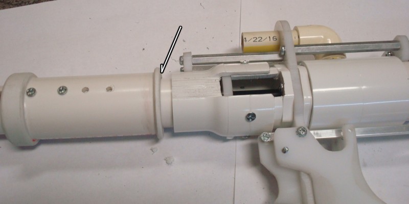
Align and press-fit the plunger tube into the back of the Grip assembly.
Use a block of wood and a hammer to tap the plunger tube into the back of the coupler until it's bottomed out inside. Attach the Upper Stock Rod to the RodAdapt part using a 1/2" length screw. The Upper Stock Rod should be flush with the back of the plunger tube. If it is not, then the plunger tube is either not completely bottom out in the coupler, or the plunger tube was cut slightly too long. Apply Silicone Grease to the head of the Plunger assembly and load it into the back of the plunger tube. Add the main spring behind the plunger. Press the Stock assembly into the back of the plunger tube. Attach the Stock assembly to the Upper Stock Rod using a 1/2" length screw. Attach the Lower Stock Rod to the Grip assembly using four 1/2" length screws. |
Step Thirty Five |
|
Remove the left Grip panel and add an extensions spring inside the Right Grip panel using a 3/8" length screw.
Also thread a 1-1/2" length screw into the Right Grip panel where the Trigger1 piece will pivot and add a 1/4" length spacer. Only install this screw as far as shown. |
Step Thirty Six |
|
Add a 3/8" length screw to the right side of Trigger 1 where shown.
Feed the free end of the extension spring through the opening in FRAME1 and hook it onto the screw on the right side of the trigger. |
Step Thirty Seven |
| Fish the trigger in through the hole in FRAME1 then place it onto the exposed end of the 1-1/2" length screw. |
Step Thirty Eight |
|
Feed the front end of Trigger Link through the assemblies until it's roughly in the spot shown.
Attach the back of Trigger Link to Trigger2 using a 3/8" length screw. DO NOT OVER-TIGHTEN THIS SCREW. Reseat the Catch plate and Trigger2 pieces so that they are engaging each other. Attach the front Trigger Link to Trigger1 using a 3/8" length screw. DO NOT OVER-TIGHTEN THIS SCREW. Test the assembly to confirm that Trigger1 is actuating the Catch Plate correctly. |
Step Thirty Nine |
|
Cut a 14-1/4" length piece of 1/2" OD Delrin Rod. This will be your Pusher Rod.
Drill a 5/16" to 3/8" diameter hole into one end of the Pusher Rod until it's 1/4" deep. Sand down the edges of this end of the rod. Drill the other end using a Drill Press and a #36 drill bit to a depth of atleast 1/2" Use a #6-32 Tapping Bit and a Tapping Wrench to add a thread to that hole. |
Step Forty |
|
Slide the PusherMidWasher onto the end of the Pusher Rod.
Secure the PusherEndCap onto the end of the Pusher Rod using a 1/2" length screw. Sand the "arms" of both pieces until the fit inside of the Pump Grip. Secure them to the Pump Grip using four 3/8" length screws. |
Step Forty One |
|
Slide the Pump Grip assembly to the end of the slot cut into the Front Tube to check fit.
Attach the Barrel Holder assembly to the end of the Front Tube using two 3/8" length screws. Recheck the Pump Grip in the cut slots and make sure that it slide freely. Use a fine-point permanent marker to mark any locations along the slot that are binding. Remove the Barrel Holder and Pump Grip assemblies then touch up those locations with a half-round rasp. Repeat this process until the Pump Grip slides freely in the slots. |
Step Forty Two |
|
Apply some Silicone Grease to the end of the Pusher Rod.
Slide the Pusher Rod into the Flanged Thrust Bearing using the slot to see what you are doing. Slide it into the u-cup washer until you feel it hit the resistance of the plunger and main spring. Align the Barrel Holder with the 1/2 CPVC Elbow, then slip the Front Tube into the Reducing Coupler and firmly seat the two halves of the Blaster together. |
Step Forty Three |
|
Push the Pump Grip all the way to the back of the slot and confirm that the Plunger is engaging in and locking with the Catch Plate.
If the Plunger is not reaching the Catch Plate when the Pump Grip is pulled all the way back, remove the Barrel Holder from the end of the Front Tube then slide the Pump Grip out. Unscrew the Pusher Rod from the Pump Grip Assembly and then use a Band Saw or Half-Round rasp to cut 1/8" of material (or as much as needed) from the back of the Pump Grip. Reassemble and test again. Repeat prior steps until the Pump Grip pushes the Plunger far enough to consistently lock into the Catch Plate. |
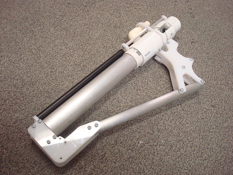
FINISHED |
Just add a barrel/hopper. |