Durendal |
| Main Project Aim: Lower Part count when compared to Plusbow, and therefore lower time investment.
Secondary Project Aim: + Offer multiple plunger tube lengths + Omni-directional catch + Impressive durability + Ease of disassembly + Low total weight + NO INTERNAL CUTS + Much more comfortable grip + Far fewer tapped holes + Option for making grips out of hardwood + Optional stock If you have any question you can contact me through: captainslg@aol.com |
Construction |
|
Essential Tools + Band Saw or Scroll Saw + Drillpress or Power Drill + 9/16" & 5/8" size flat-blade wood-boring drill bits + Mitre Box & Mitre Saw + #6-32 Tapping Bit + Fine-Point Permanent Marker + Tri-point ruler + Screwdriver + Half-Round Rasp + 300 grit sandpaper + Hobby Knife (to clean the edges of the sheets once cut) + Scissors + Inkjet or Laser printer + Packet of full-sheet label paper (Avery 8165) + Electrical tape + Face Shield or Safety glasses + Silicone Grease + Vice or C-Clamp + Bolt Cutters + Scotchbrite Pad + Deburring Tool or Countersink + Pick, Tweezers, or Hemostats No other tools expressly needed. All tools listed are not easily substitutable. Part List Download: durendal_partlist.xls All items available through http://www.mcmaster.com A full set of prices is included. Simply copy and paste the first two columns into the text box of the McMaster Carr "Build Order" page. It may be possible to purchase the majority of the parts from a local hardware store. Lowe's and Home Depot both carry threaded rod in the required size as well as Cross Dowel Nuts. However prices for those items at Home Depot are very high, and inventory of polycarbonate is very inconsistent between different locations. Lowe's has far more competitive prices, expecially on the Cross-Dowel Nuts. |
Step One |
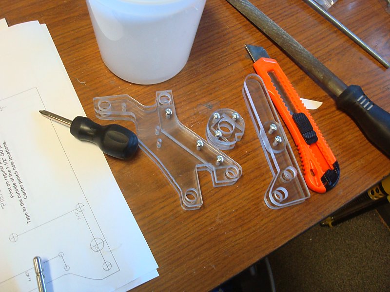
| Download the cutting template sheets: durendal_templates.doc Print PAGE 1 on full sheet label paper. The included legend will tell you what size holes need to be drilled where. Most of which are labeled with the bit size or tapping requirements. Any unspecified holes should be drilled for clearance of a #6-32 screw (typically a #23 or 5/32). The parts inside the lined box are vital. The parts outside of that box only need to be made if you want to add a stock. The rest of the pages can be printed on regular paper. Three different plunger tube lengths are available. Using a Hammer and a Center Punch (or a Nail) put a centering divot on the centermark of every hole on every part template. |
Step Two |
| Using a Drill Press drill all of the holes labeled as "#6-32" with a #36 or 7/64" drill bit. |
Step Three |
|
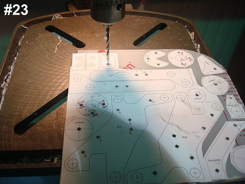
Using a Drill Press drill all of the holes labeled as "#23" with a #23 drill bit.
|
Step Four |
|
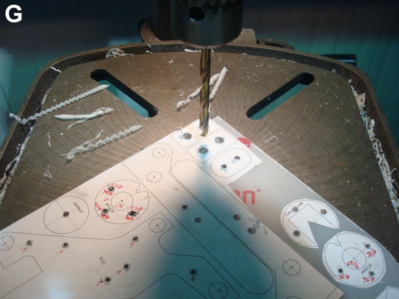
Using a Drill Press drill all of the holes labeled as "G" with a Letter G drill bit.
|
Step Five |
|
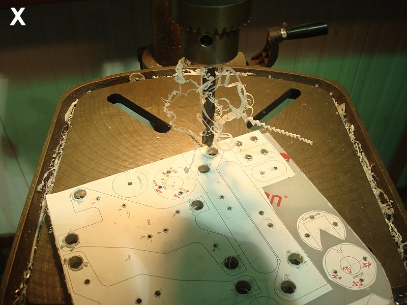
Using a Drill Press drill all of the holes labeled as "X" with a Letter X drill bit.
|
Step Six |
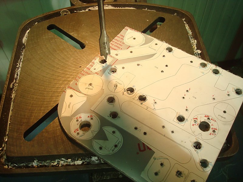
| Using a Drill Press and a 9/16" Flat Wood-boring drill bit bore out all the holes labeled "9/16". Go slowly and carefully with minimal downforce to help avoid tearing the templates off the plastic. |
Step Seven |
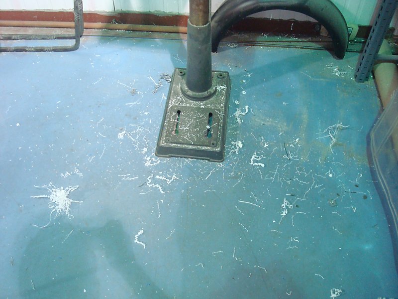
| Now you have a mess you need to clean up. |
Step Eight |
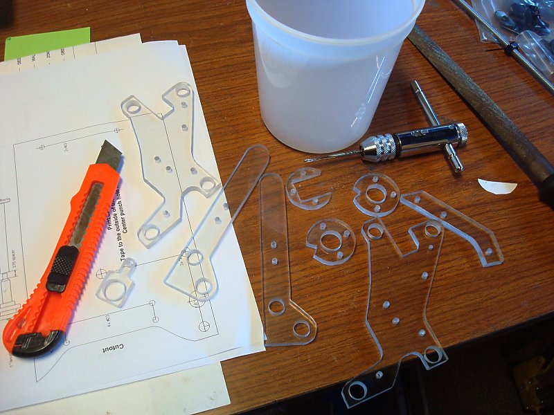
| Using a Scroll Saw or a Band Saw coarsely cut all of the parts free from the plastic sheet. |
Step Nine |
| Add as many relief cuts as you think are needed. A relief cut is a cut made perpendicular to the intended cutting line that allows excess material to break away as the cut is made along the intended contour. |
Step Ten |
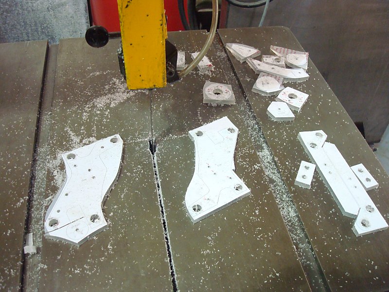
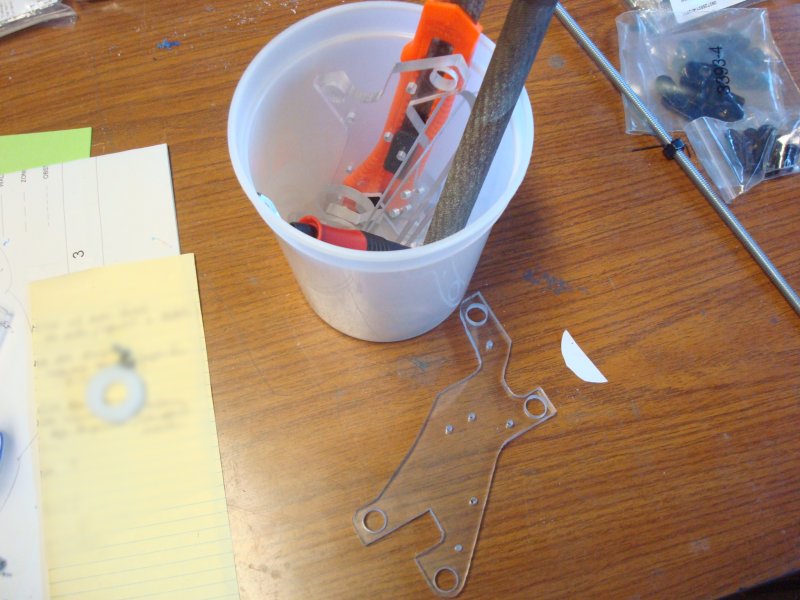
| Using a Scroll Saw or a Band Saw accurately cut all of the parts to their outlines.
|
Step Eleven |
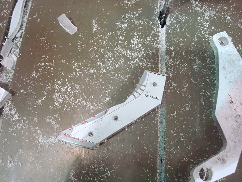
| And now you have another mess you need to clean up. |
Step Twelve |
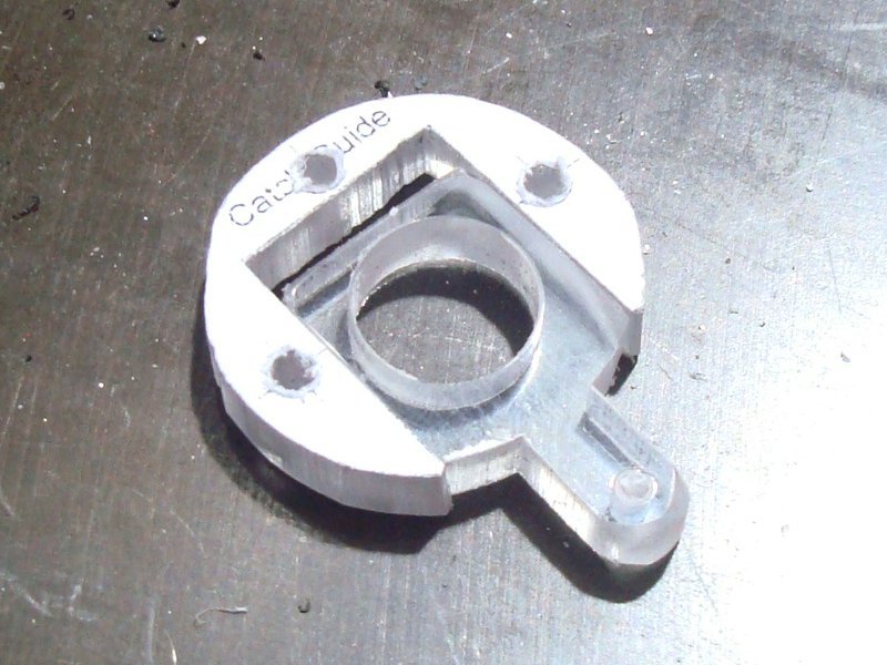
| Check the fit between the Catch Plate and Catch Guide pieces. Sand the sides of Catch Plate until the parts can slide easily |
Step Thirteen |
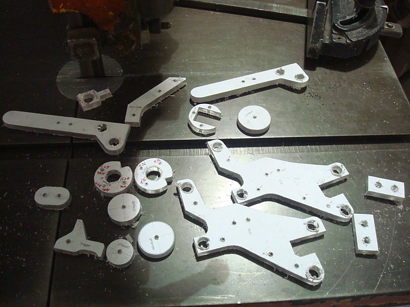
| Using a Hobby Knife deburr all the cut edges of the now mostly-finished pieces.
Sand any rough spots with a Half-Round Rasp. |
Step Fourteen |
| Use a #6-32 Tapping Bit and Tapping Wrench to add a thread to all of the #36 holes. |
Step Fifteen |
|
Do a test assembly of the Grip, Catch Parts, and Stock. Use 5/8" Length Screws for each. If you are making the grip out of hardwood you can use wood glue to permanently fuse the Grip components. You can do the same with the plastic Grip components using Super Glue. BUT DO NOT GLUE THE STOCK COMPONENTS TOGETHER. The Stock assembly needs to be able to be taken apart and put back together multiple time later on in order to assemble the stock to the correct length. |
Step Sixteen |
|
Use a Half-Round Rasp or Belt Sander to round of the backstrap and side panels of the Grip. Also round of the front edges of the grip panels. Continue this process until you are satisfied with the comfort level of the grip assembly. Use 300 grit sandpaper to sand all of the edges until it's comfortable enough for you to hold tightly. After this process one or more of the screws may need to be replaced. You will not need to keep the uppermost screw in the backstrap for later use, and can leave it out of the final assembly. |
Step Seventeen |
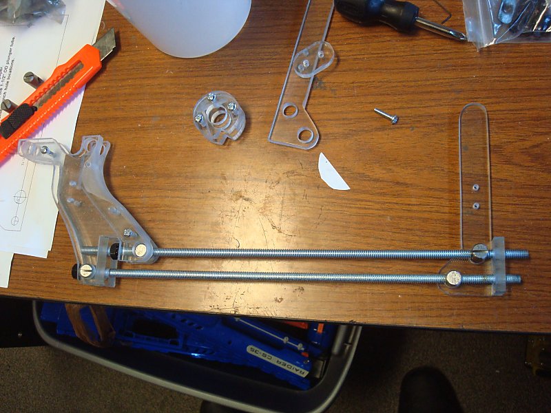
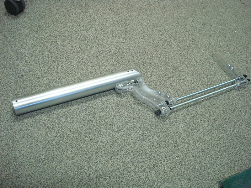
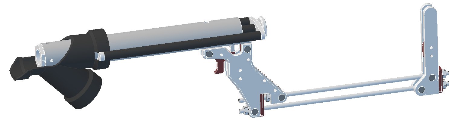
| If you are not adding the Stock, skip to Step # 19 Assemble the Stock as shown by inserting two Cross-Dowel Nuts into the holes in the Grip Assembly. Screw the upper Threaded Rod into the upper Cross-Dowel Nut, then onto a hex nut, then through the Stock Washer. Slide the lower Threaded Rod through the Stock Washer, then screw it into the lower Cross-Dowel Nut, then thread a hex nut onto the end. Screw a Cross-Dowel Nut onto the far end of each threaded rod and match the spacing shown as close as you can manage. Use one of the Stock Panels as a guide to get the spacing correct. Also confirm that the Stock Panel is upright relative to the Grip assembly. Adjust the location of the Cross-Dowel nuts until alignment is correct. Slide the remaining Stock Washer onto the end of the Threaded Rods. |
Step Eighteen |
|
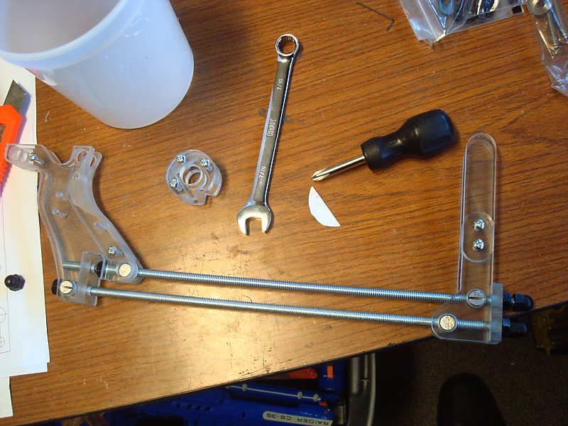
Screw a hex nut onto the end of each Threaded Rod. Use a 7/16 wrench to tighten all of the Hex Nuts. Check the feel of the stock and grip spacing for comfort and distance. Adjust the stock to a different position if needed by removing Stock Sides and tightening or loosening the Cross-Dowel nuts on both Threaded rods. Reassemble the Stock Sides then tighten the hex nuts again. You can either cut the remainder of the threaded rod off just beyond the hex nuts, or cap the ends with acorn nuts. |
Step Nineteen |
| Select the length of Plunger tube you intend to base your blaster around. Use a Fine-Point Permanent Marker and a Ruler to place multiple marks along its circumference on the plunger tube material at the length of the desired Plunger Tube. |
Step Twenty |
|
Use Scissors to cut the Plunger Tube template out of the page. Wrap the template around the plunger tube keeping the template lined up with the end of the plunger tube material. Secure it in place with several small pieces of Electrical Tape. Use a Center Punch and a Hammer to mark divots on all of the hole centers on the template. |
Step Twenty One |
|
Use a Band Saw or a Hack Saw to cut the Plunger Tube to length. Then cut off the area marked CUTOUT. |
Step Twenty Two |
| Using a Drill Press drill all of the holes with a #23 drill bit. These will act as centers for the larger hole sizes too. |
Step Twenty Three |
| Using a Drill Press drill all of the holes labeled as "G" with a Letter G drill bit. |
Step Twenty Four |
| Using a Drill Press drill the only hole labeled as "1/2" with a 1/2" drill bit. |
Step Twenty Five |
| Use a Deburring Tool, Hobby Knife, and one or many Files to remove all the burrs from the holes you just drilled and the cuts you just made. |
Step Twenty Six |
| Use a Scotch Brite Pad to clean the outside of your finished plunger tube. |
Step Twenty Seven |
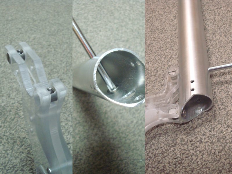
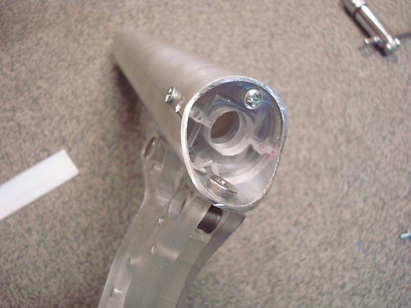
| Insert two Cross Dowel Nuts into the top of the Grip Assembly. Feed one of the 1/4-20 Screws into the furthest hole from the back end of the Plunger Tube. Slide a screwdriver in from the opposite hole, and thread the screw into the Cross-Dowel Nut at the front of the Blaster until it's tight. Install the 1/4-20 Screw for the remaining Plunger Tube hole. |
Step Twenty Eight |
| Check the alignment of the Plunger Tube and Grip Assembly. |
Step Twenty Nine |
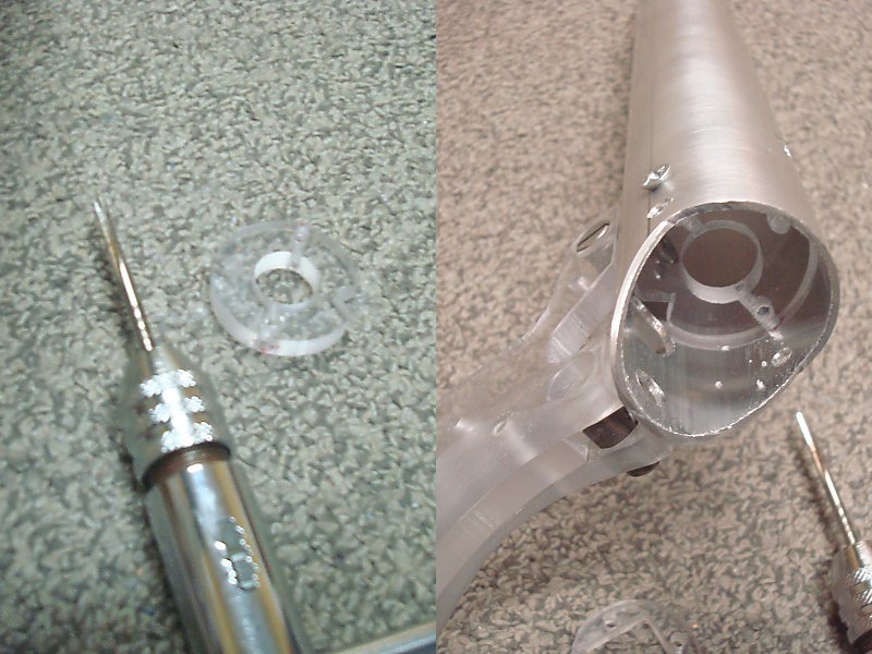
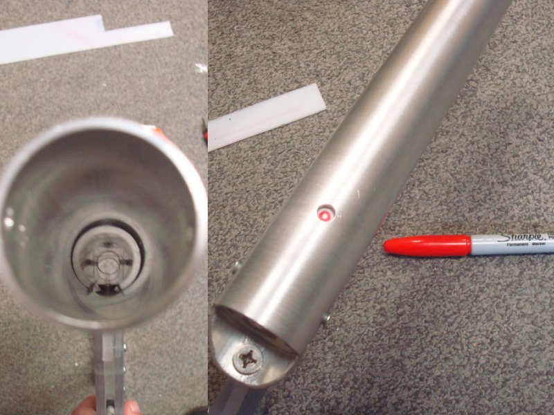
| Remove the rear 1/4-20 screw. Slide the pCross piece with threaded holes into the back of the plunger tube until it lines up with the forward pair of holes. Check the alignment of the notch with the 1/2" hole drilled into the bottom of the plunger tube. Use a Fine-Point Permanent Marker to mark the edges of the pCross piece. Take the pCross piece back out and adust the Fine-Point Permanent Marker points so that they are centered on the edges of the piece. Use a Drillpress to drill the center of these marks using a #36 drill bit. Using a Tapping Wrench and a #6-32 tapping bit, add threads to these new holes. |
Step Thirty |
|
Secure the extension spring to the Catch Plate using a 3/8" length Screw. Install the pCross piece into the back of the Plunger tube using two 3/8" length screws. Approaching at an angle, slip the spring through the 1/2" hole in the plunger tube to get Catch Plate in place. Surround the Catch Plate with the Catch Guide piece. |
Step Thirty One |
| Use a 5/8" length screw to secure the remaining pCross piece to complete the Catch Assembly in the end of the Plunger tube. Use a pair of pliers to make sure that the catch piece is able to move freely. If the Catch Plate cannot move freely you may need to remove it and sand or deburr it again. If the Cross-Dowel nut fell out of the grip at some point prior, put it back in place. Reaffix the rear 1/4-20 screw. |
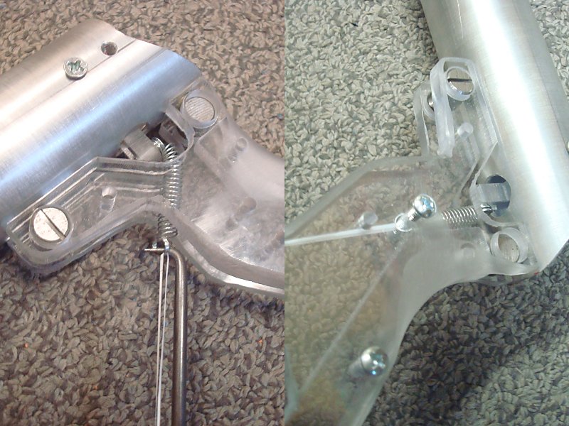
Step Thirty Two |
| Use a Pick to pull the free end of the extension spring out the front of the Grip assembly. Thread a length of string through the loop. Use the string to pull the open loop of the spring into alignment with one of the two holes in the Grip sides. Install a 5/8" length screw into the Grip and through the loop of the extensions spring. Pull the string out of the loop. |
Step Thirty Three |
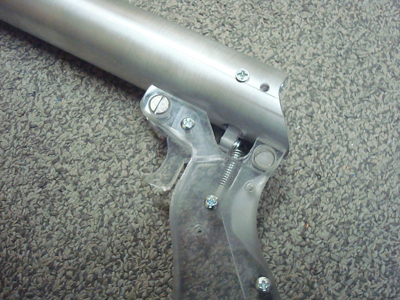
| Install the Trigger using yet another 5/8" length screw. Test the actuation of the Trigger and Catch Plate. Remove the Trigger and File or Sand it down in any spots you think might be a source of sticking or rubbing. This process may take several tries, especially if the grip and trigger are made out of hardwood. |
Step Thirty Four |
|
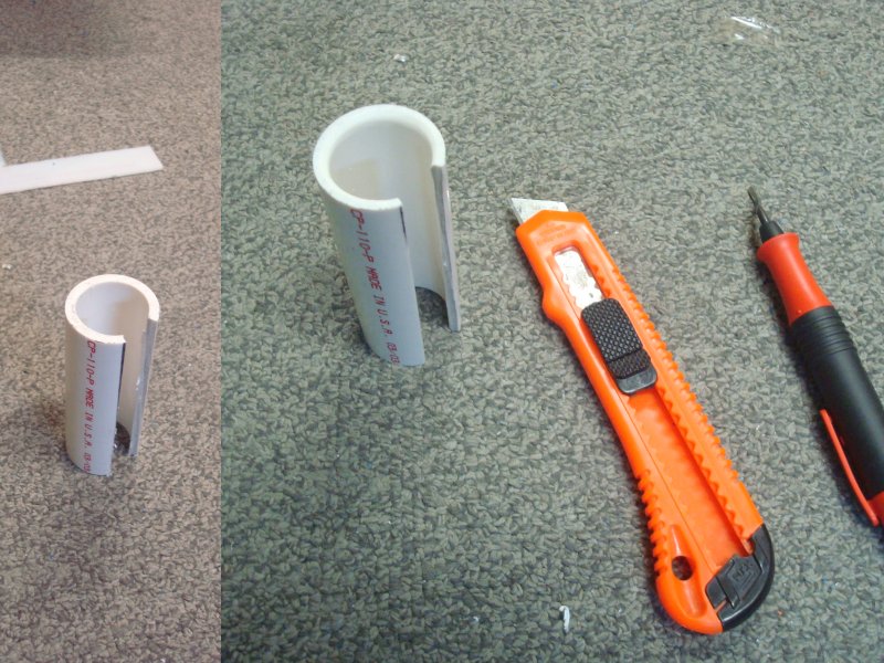
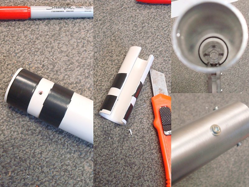
Use a Band Saw or Hack Saw to cut a short length of 1 NPS Pipe. This will become the Spring Collar. The "Rifle" Plunger tube uses a 3 inch length piece. The "Shmedium" Plunger tube uses a 2 inch length piece. The "Pistol" Plunger tube uses a 1-3/8 inch length piece. Use a Deburring Tool to chamfer both inside ends of the piece. Use a Band Saw or Hack Saw to cut a length-wise 1/2" wide slot as shown. |
Step Thirty Four |
| The
slot allows the Spring Colar to clear the lower screw inside the
plunger tube. When the Spring Collar is dropped into the plunger tube
it needs to bottom out against the Catch assembly. Use a Permanent Marker to mark the Spring Collar through the hole in the top of the Plunger Tube. |
Step Thirty Five |
| Remove the Spring Collar. Use a Drill Press and a #36 drill bit to drill the center of the mark. Use a Tapping Wrench and a #6-32 Tapping Bit to add a thread to this hole. Put 3 wraps of electrical tape around the Spring Collar next to both sides of the new tapped hole. Use a Hobby Knife to cut the electrical tape wrap where it bridges the slot. Use a Ruler or Long Screwdriver to push the Spring Collar back into the Plunger Tube. Secure it in place using a #6 washer and a 3/8" length screw. |
Step Thirty Six |
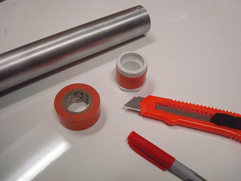
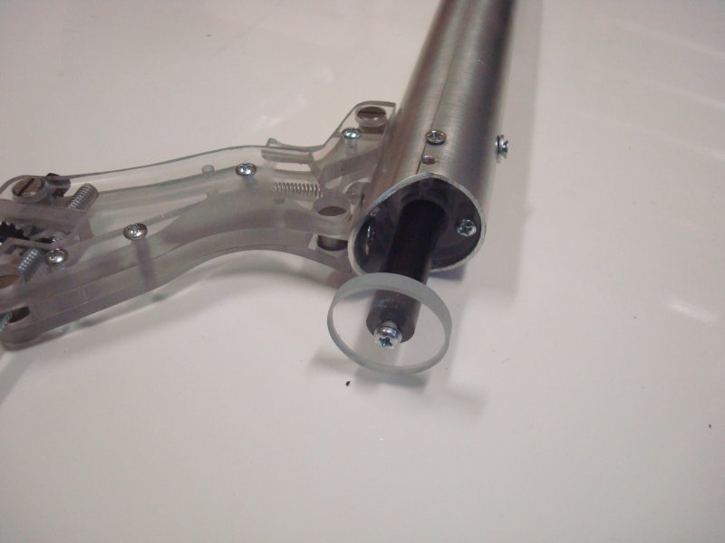
| Put 3 layers of Electrical Tape around the Bushing Adapter. |
Step Thirty Seven |
|
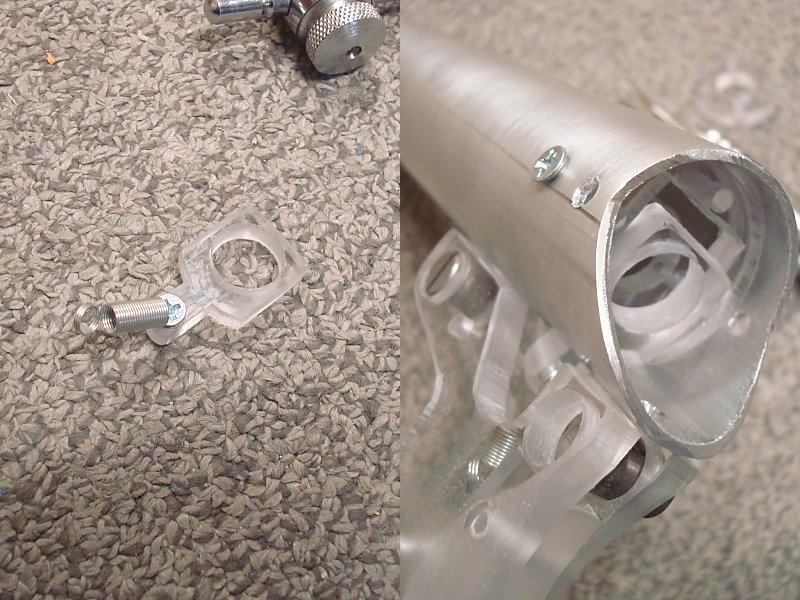
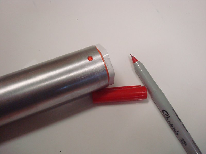
Push it into the end of the plunger tube. Use a Fine-Point Permanent Marker to mark the tape through both holes in the Plunger Tube. Use a Drillpress and a #36 drill bit to drill both holes. Use a Tapping Wrench and a #6-32 tapping bit to add a thread to both holes. Remove the Bushing Adapter from the Plunger Tube and set it aside. |
Step Thirty Eight |
| Following
the measurements provided for the Plunger assembly that goes with each
available Plunger Tube Size, cut the two length of Plunger Rods. Use a Drillpress and a #36 drill bit to drill the center of both ends of each Plunger Rod Piece. Use a Tapping Wrench and a #6-32 tapping bit to add a thread to all of these holes. Check the fit of the pHead2 piece inside of the plunger tube. If the piece does not fit and does not slide easily make sure to sand it down until it does. Also sand a chamfered edge onto one end of the shorter Plunger Rod. |
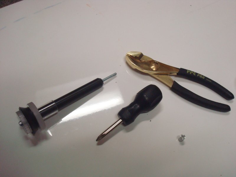
Step Thirty Nine |
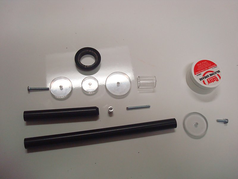
| Use Bolt Cutters to cut the head off of a 1-1/4 or 1-1/2 inch length screw. Use a File to file down the burrs on the cut end of this headless screw until the thread starts cleanly. Use Pliers to install this short threaded rod into the chamfered end of the shorter Plunger Rod. Attach all of the pHead parts and the skirt seal onto the end of the shorter Plunger Rod using a 1-1/4" length screw. An optional spring centering piece can be added behind the plunger head. |
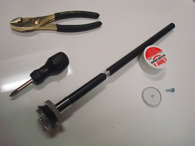
Step Forty |
|
Slide the 3/8" length spacer onto the threaded rod. Screw the threaded rod into the end of the longer Plunger Rod. |
Step Forty One |
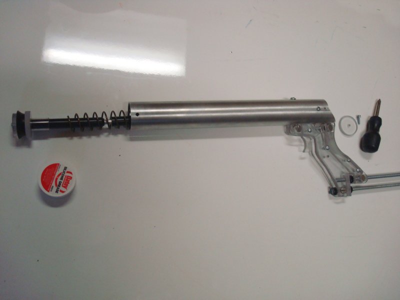
| Each Plunger Tube length requires a different cut length of main spring. The "Rifle" Plunger Tube can use a full-length 11 inch spring. The "Shmedium" Plunger Tube needs the spring cut down to an 8 inch length. The "Pistol" Plunger Tube needs the spring cut down to a 5-1/2 inch length. Use Bolt Cutters to cut the spring to the required length. Slide the spring into the plunger tube. Use your finertip to add plenty of Silicone Grease to the edge of the skirt seal. Feed the plunger tube into the Plunger Tube and into the Catch Assembly. Press the Trigger while feeding the Plunger Rod through the Catch Plate. |
Step Forty Two |
|
Use a 1/2" length screw to secure the pHandle to the end of the Plunger Rod. If you only have 3/8" length screws available the center hole in pHandle will need to be countersunk. |
Step Forty Three |
| Push the Bushing Adapter into the end of the Plunger Tube and secure it with #6 washers and 3/8" length screws. Add a Barrel of your choice. |
PUMP-GRIP INSTRUCTIONS WILL BE AVAILABLE SOON |