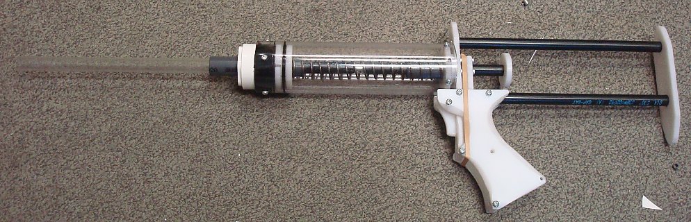
Plusbow Rev.3 |
| Main Project Aim: Reduce Part count
Secondary Project Aim: + Two Options for Plunger tubes and Plungers (+bow or 2-11) + Omni-directional catch + Spring guide to remove "serpentine" behavior + Ease of disassembly + Limit screws to two lengths (1/2" and 1-1/2") + "Check Valve" Plunger head + Use of extensions springs or rubber bands for catch (multiple configurations possible) + "Ultra-Compressible" O-Rings + NO MORE INTERNAL CUTS, that means no pilot holes, no feeding a scroll saw blade through a pilot hole. Every cut can be done with a scroll saw or a band saw. Nerfhaven Forum Thread If you have any question you can contact me through: captainslg@aol.com |
Construction |
|
Essential Tools + Band Saw or Scroll Saw + Drillpress or Power Drill + 9/16" & 5/8" size flat-blade wood-boring drill bits + Mitre Box & Mitre Saw + #6-32 Tapping Bit + Fine-Point Permanent Marker + Screwdriver + Half-Round Rasp + 300 grit sandpaper + Bolt cutters (for cutting spring) + Hobby Knife (to clean the edges of the sheets once cut) + Scissors + Inkjet or Laser printer + Packet of full-sheet label paper + Electrical tape + Face Shield or Safety glasses + Super Glue + Silicone Grease + Vice or C-Clamp No other tools expressly needed. All tools listed are not easily substitutable. You can cut out the center of one part using a Scroll Saw or Coping Saw, and a Band Saw could be used to make the external cuts more quickly. Part List Download: bow3_partlist.xls All items available through http://www.mcmaster.com A full set of prices is included. Simply copy and paste the first two columns into the text box of the McMaster Carr "Build Order" page. All items on the "Grip" page are essential. The other two pages provide you with plunger tube options. The "+bow" plunger and plunger tube have a 6.25" draw at a maximum of 35 pounds with a smaller working volume. The "2-11" plunger and plunger tube have a 4.5" draw at a maximum of 29 pounds with a larger working volume. Each option has very similar performance. |
Step One |
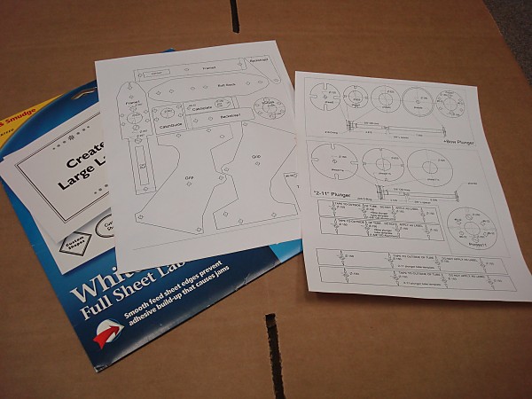
| Download the template sheets: bow3.doc Print them on full sheet label paper. The included legend will tell you what size holes need to be drilled where. Most of which are labeled with the bit size or tapping requirements. Any unspecified holes should be drilled for clearance of a #6-32 screw (typically a #23 or 5/32). There are two plunger tube options available, so select the size you intend to make and apply that extra page of labels as well. |
Step Two |
|
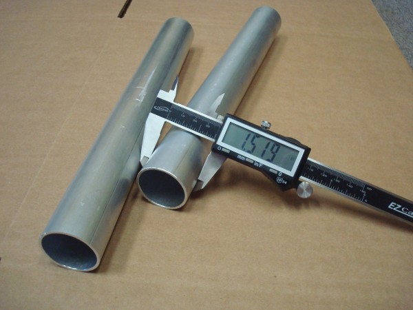
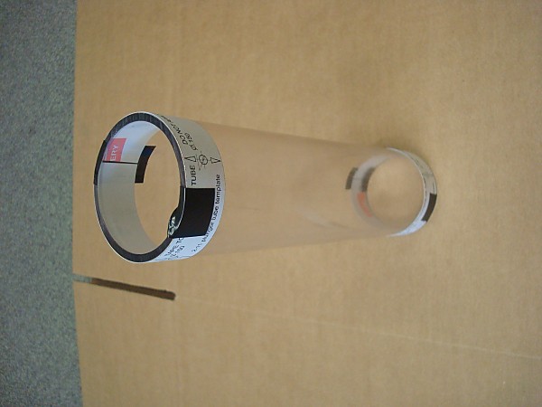
The templates used for drilling the plunger tubes are only likely to work perfectly for you if the plunger tubes you are supplied have a diameter matching the measurement used to make the template. So the "+bow" plunger diameter template was made for a 1.52" OD Aluminum tube and the "2-11" plunger tube was made for a 2.25" OD polycarbonate tube.
Any alternate material used to make your plunger tubes that has a different outer diameter will not be able to make use of these templates. An alternate material to use for making the "+bow" plunger tube is 1-1/4 SCH40 PVC pipe which has an outer diameter of 1.66". Making your own templates of this type however is quite easy. You simply take the diameter of the tube you intend to use, convert it to its circumference, then divide that circumference by 4 and that's what you hole spacing should be measure out to on the outside of that material using a flexible measuring tape. It's also worth noting that most "1/4" Polycarbonate sheets do not come in a thickness that is exactly 0.250", but rather measure at 0.230". This difference in thickness impacts the spacing away from the end of the plunger tubes that these holes need to be drilled to. |
Step Three |
|
The "+bow" plunger tube you will need to use a mitre saw or a band saw to cut a 12"-long piece of the 1-1/2" OD aluminum tubing. After doing so deburr the edges of the tube. The "2-11" plunger tube will need to be cut down to 8-1/2" in length using a a mitre saw or a band saw. The cut edges will need to be deburred using a box cutter or hobby knife. Apply the appropriate template to your selected plunger tube ends. Make sure to apply these temporarily using tape and NOT BY USING the label paper itself. Tape will be easier to later remove, where-as the label paper can sometimes be difficult to get back off. If the cut ends of the template do not come close to meeting each other or overlap too much then your drilled holes will not be spaced evenly at 90-degrees. The impact of this will be discussed later. |
Step Four |
|
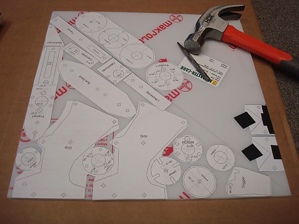
You can trim them apart to try to fit all the parts into the space available on the sheet you have, otherwise simply adhere the entire label set onto your plastic sheet after trimming off the edges. Also apply the parts for the matching pump-action grip if you intend to make that as well. Using a Hammer and a Center Punch (or a Nail put a centering divot on the centermark of ever hole on every part template. |
Step Five |
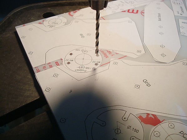
| Using a Drill Press drill all of the holes labeled as "#6-32" with a #36 or 7/64" drill bit. Then drill all the unlabeled holes with a #23 or 5/32" drill bit. |
Step Six |
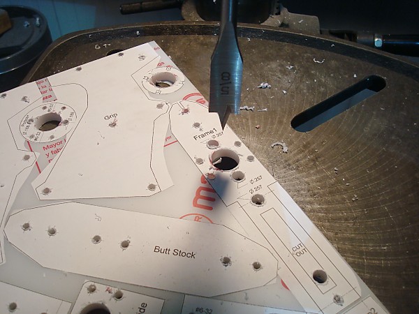
| Using a Drill Press and a 9/16" Flat Wood-boring drill bit bore out all the holes labeled "9/16". Go slowly and carefully with minimal downforce to help avoid tearing the templates off the plastic. |
Step Seven |
| Using a Drill Press and a 5/8" Flat Wood-boring drill bit bore out all the holes labeled "5/8". Go slowly and carefully with minimal downforce to help avoid tearing the templates off the plastic. |
Step Eight |
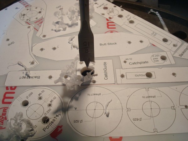
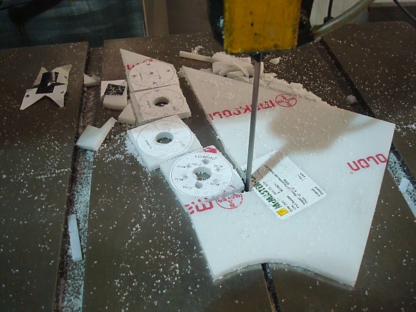
| Using a Scroll Saw or a Band Saw coarsely cut all of the parts free from the plastic sheet. |
Step Nine |
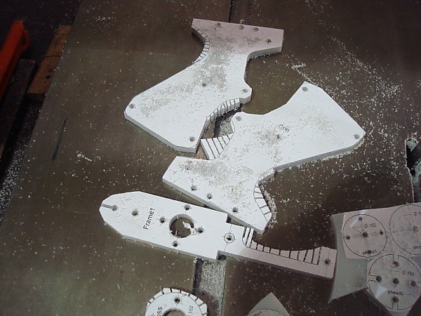
| Add as many relief cuts as you think are needed. A relief cut is a cut made perpendicular to the intended cutting line that allows excess material to break away as the cut is made along the intended contour. |
Step Ten |
|
Using a Scroll Saw or a Band Sawmore accurately cut all of the parts to their outlines.
Using a Hobby Knife deburr all the cut edges of the now mostly-finished pieces. |
Step Eleven |
|
Using a Fine-Point Permanent Marker draw a line on the edges of the now cut parts whereever a dotted line meets the edge of the template.
Also mark a perpendicular line as close to the approximate center point of the edge of the piece. |
Step Twelve |
|
Drill all of these new center marks with a a #36 or 7/64" drill bit.
Using your #6-32 tapping bit and a Tapping Wrench tap all of the holes you previously drilled with a #36 or 7/64" drill bit. If needed, lubricate your tapping bit with common dish soap. |
Step Thirteen |
| Use Super Glue and a C-Clamp to glue together the three plunger head parts that match your chosen plunger type. Make sure to line up the center hole on all three pieces as well as the "check valve" holes. |
Step Fourteen |
|
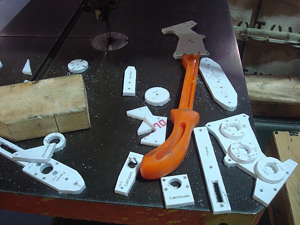
Remove all of the template labels and protective film from your plastics parts.
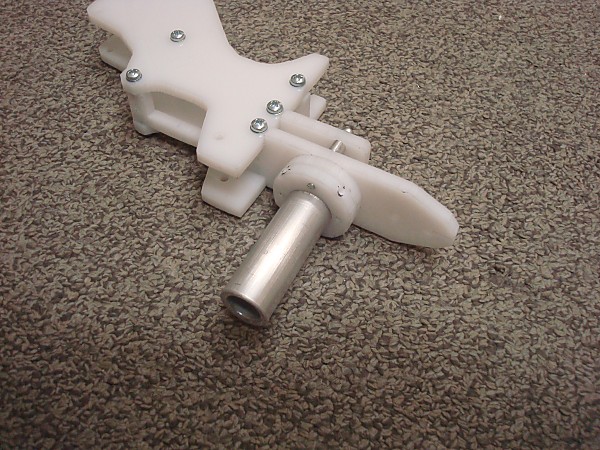
Do a test assembly of the Grip with the components as shown. Using a Half-Round Rough File (Rasp) or Belt Sander or a Router soften all of the edges of the test assembly to suit your preferences regarding fit and comfort with your hand. Cut away and excess material as desired using a Scroll Saw or Band Saw. |
Step Fifteen |
|
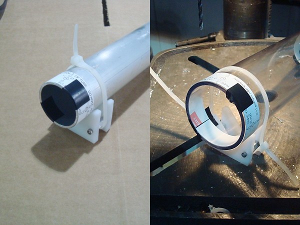
Using 1/2" screws and the 1-inch long threaded spacers assemble the "V-Block" parts.
Use a few Zip Ties to clamp the "V-Block" onto the end of the plunger tube near the template. |
Step Sixteen |
|
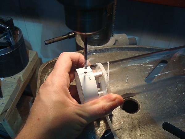
The V-Block will help you keep the plunger tube stable so that you can drill the hole out using a #23 or 5/32" drill bit.
Rotate the plunger tube to the next center mark and drill the next holes, then repeat the process. Slide the V-Block down to the opposite end of the plunger tube and repeat the process again. |
Step Seventeen |
|
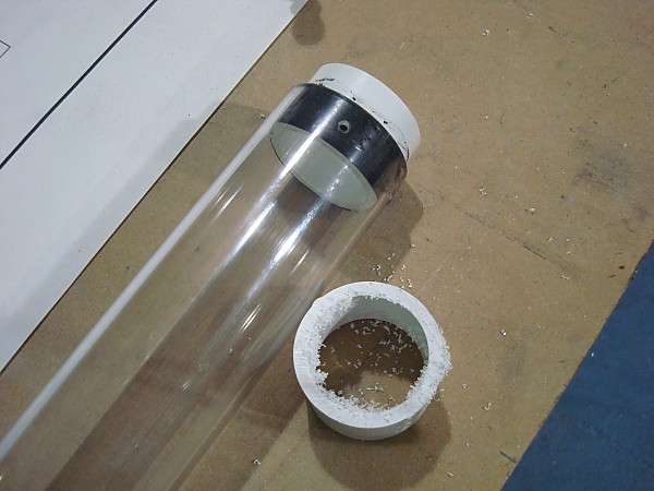
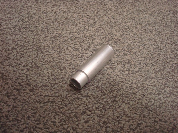
For the "2-11" style plunger tube use a Mitre Saw or a Band Saw to cut the 1-1/4 SCH40 Pipe coupler in half along the mold seam.
Put two wraps of e-tape around the end near the cut, then slide it into the end of the plunger tube. Tap the 1-1/4 SCH40 Bushing adapter into the coupler half. Use a #36 or 7/64" drill bit and a Drill Press to drill these holes into the PVC components. Using your #6-32 tapping bit and a Tapping Wrench tap all of these holes. Then install 1/2" length screws. You may want to use a 1-1/2" length screw in one of the holes as a safety measure to prevent darts from being suction-loaded into the plunger tube. |
Step Eighteen |
|
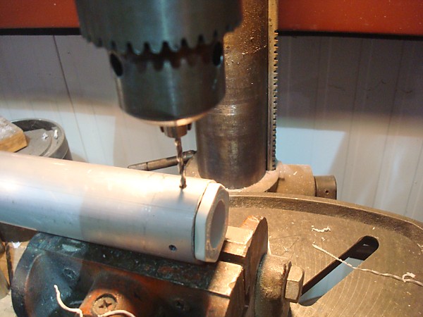
For the "+bow" style plunger tube wrap the 1-1/4 SCH40 bushing in 4 to 6 layers of e-tape until it fits the aluminum tube snugly. Insert it all the way into one end.
Use a #36 or 7/64" drill bit and a Drill Press to drill these holes into the bushing. Using your #6-32 tapping bit and a Tapping Wrench tap all of these holes. Then install 1/2" length screws. You may want to use a 1-1/2" length screw in one of the holes as a safety measure to prevent darts from being suction-loaded into the plunger tube. |
Step Nineteen |
|
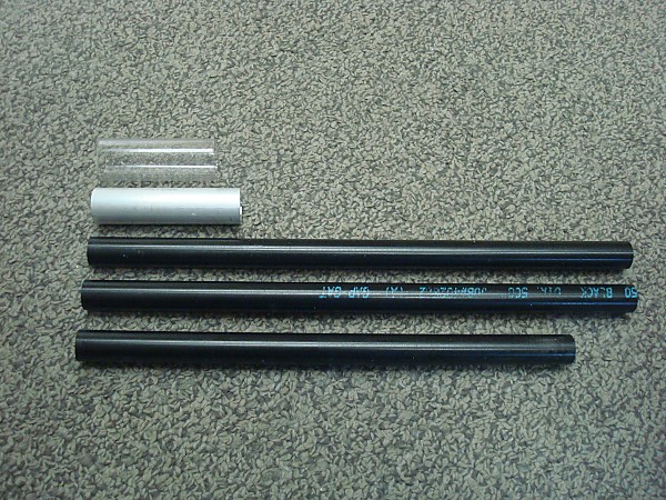
Using a Mitre Saw or Band Saw cut the lengths of 1/2" Plastic rod as specified by the cross-section drawings that were included with the template sheet for the plunger type you selected. Those lengths are.
"+bow" type: 4-3/8" and 7-1/2" "2-11 type: 2-5/8" and 6" For the Stock: 9-3/8", 9-1/4", and 8" Use a #36 or 7/64" drill bit and a Drill Press to drill the centers of both ends of each length of rod. Also follow the dimensions listed in Template Sheet 4 to drill and tap the holes in the sides of the rods. Using your #6-32 tapping bit and a Tapping Wrench tap all of these holes. From the 5/8" OD Aluminum cut: 2-1/2" and 1/2" From the 3/4" OF Polycarbonate cut: 1-3/4" and 1/2" |
Step Twenty |
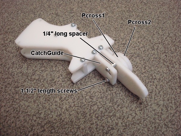
| Fully assemble the Grip. Pcross2 should be the part from the plugner tube you selected. |
Step Twenty One |
|
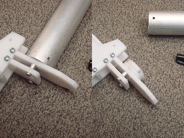
Test fit your plunger tube over the Pcross parts, then use a Fine-Point Permanent Marker to label the hole locations on Pcross2.
Use a #36 or 7/64" drill bit and a Drill Press to drill these holes in the center of the edge of Pcross2. Using your #6-32 tapping bit and a Tapping Wrench tap all of these holes. |
Step Twenty Two |
|
THIS STEP ONLY APPLIES TO THOSE THAT INTEND TO BUILD THE BLASTER WITH A K25 SPRING. If you intend to use a K26 spring you can skip this step.
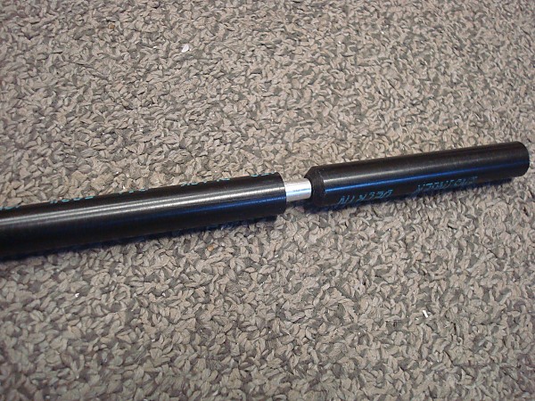
Use a Vice or a C-Clamp to press the 1-3/4" length of 3/4" OD polycarbonate onto one end of the 2-1/2" length of 5/8" OD aluminum tube. |
Step Twenty Three |
| Install the combined piece into the Grip assembly. You may need to use the Vice or C-Clamp again. |
Step Twenty Four |
| Use your #6-32 tapping bit and a Tapping Wrench to tap all of those holes.
Use some Bolt Cutters to snip the head off of a 1-1/2" screw. Use the now headless 1-1/2" and the 3/8" length spacer to assemble the two plunger rod halves together as shown. |
Step Twenty Five |
|
IF YOU ARE USING A K25 SPRING YOU WILL WANT A 3/4" OD piece for centering purposes on your plunger rod. If you intend to use a K26 spring you will want a 5/8" OD piece on your plunger rod.
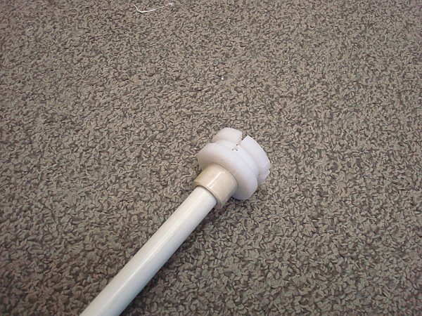
For a K25 spring: Use a Vice or a C-Clamp to press the 1/2" length of 3/4" OD polycarbonate onto one end of the 1/2" length of 5/8" OD aluminum tube. For a K26 spring: Super glue just a short piece of 5/8" OD aluminum tube. Install the spring centering piece onto the front end of the plunger rod. Then attach the plunger head using a 1-1/2" length screw. Use Super Glue to adhere the spring centering piece to the backside of the plunger head. Wait 30 minutes for the adhesive to fully set. Add the size Ultra-Compressible O-Ring designated for that Plunger Rod size. |
Step Twenty Six |
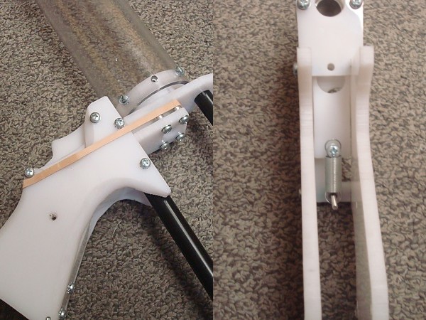
| Remove the Frame2 part from the Grip assembly.
Slide the CatchPlate up into the grip assembly. You can use a rubber band on the outside of the assembly as a cheap return spring. Or an extension spring on a 1/2" (or longer) screw with the other end looped onto a 1-1/2" (or longer) screw held to Frame1 using a hex nut or a spacer. Install the Trigger using a 1-1/2" screw. |
Step Twenty Seven |
| Attach the Middle Stock rod to Frame2 using a 1/2" length screw, then re-install Frame 2 into the Grip Assembly using four 1/2" length screws.
Assemble the rest of the Stock Parts onto the Grip Assembly as shown. The upper stock rod has two installation locations that you can choose from based on personal preference. |
Step Twenty Eight |
| Coat the head of the plunger with Silicone grease.
Install the Plunger Rod and Main Spring in the Plunger Tube. Work the Plunger Rod back and forth in the Plunger Tube until it's fully lubricated. Slide the assembled plunger tube onto the Grip Assembly by feeding the Plunger Rod through it while holding the Trigger. Attach the plunger tube to the front of the grip assembly using 1/2" screws. Install the Phandle onto the Plunger Rod using a 1/2" screw. You are finished. Just add a barrel of your choice. |
Step Twenty Nine (OPTIONAL) |
|
Cut two 1/2" delrin rods to 8-1/2 inches in length.
Drill both ends of each rod with a #36 or 7/64" drill bit. Drill at minimum 5/8" deep. Tap those holes with a #6-32 tapping bit using a Tapping Wrench. |
Step Thirty (OPTIONAL) |
|
Using the foregrip piece as a template, mark where the "ears" of it stick out relative to the 1-1/2 DWV Wye fittings.
Use a Scroll Saw or a Band Saw to cut a 1/2" wide slot into both sides of the back sdie of the 1-1/2 DWV Wye fitting as shown. Use a Scroll Saw or a Band Saw to cut the back off of the 45-degree leg on the 1-1/2 DWV fitting as shown so that it will clear the area where your trigger finger is likely to be when you cycle the grip back on the plunger tube. Sand the outside curvature of the foregrip piece until it fits snugly inside the back end of the 1-1/2 DWV Wye fitting, then use Super Glue to permanently adhere it there. |
Step Thirty One (OPTIONAL) |
|
You may need to remove the bushing from the front end of the plunger tube in order to slide the 1-1/2 DWV fitting with foregrip plate inside of it onto the plunger tube.
Using a half-round rasp, sand the inside of the foregrip plate until the foregrip can slide easily over the outside of the plunger tube. Use 1/2" length screws to attach the 8-1/2" length rods to the foregrip. Remove the "pHandle" piece from the back of the plunger rod. Then Slide the rear foregrip piece onto the plunger rod. Re-attach the "pHandle" piece to the plunger rod. Use 1/2" length screws to attach the 8-1/2" length rods to the rear foregrip piece. This completes the optional pump-action grip assembly process. |
FINISHED |