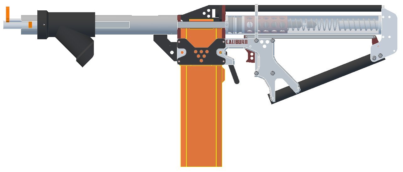
CALIBURN |
| Main Project Aim: Mag-Fed Pump-Action Springer
Length: 31 inches Weight: 2 1/2 pounds (empty) Muzzle Velocity with O-Ring: 210 fps max Muzzle Velocity without O-Ring: 160 fps max Secondary Project Aim: + Low Total Weight + Omni-directional catch + "Wiffle Tube" floating plunger head + Floating Plunger Tube + Ease of Disassembly + NO INTERNAL CUTS. If you have any question you can contact me through: captainslg@aol.com This project is VERY time-consuming and can take upwards of 24 hours to complete. Take your time and work carefully because the tolerances on some of the parts are important for assembly to work properly. |
Construction |
|
Essential Tools + Band Saw or Scroll Saw + Drillpress + 1/4", 9/16", 5/8", & 1-1/2" size flat-blade wood-boring drill bits + Machine Lathe (or contracted service) + #6-32 Tapping Bit + Fine-Point Permanent Marker + Tri-point ruler + Screwdriver + Half-Round Rasp + 300 grit sandpaper + Deburring Tool + Hobby Knife + Scissors + Inkjet or Laser printer + Packet of full-sheet label paper (Avery 5265) + Electrical tape + Super Glue + PVC Cement + Silicone Grease + Vice or C-Clamp + 3/4" OD 82 Degree Countersink + Scotchbrite Pad + Face Shield or Safety glasses + Hearing Protection No other tools expressly needed. All tools listed are not easily substitutable. Part List Download: caliburn_parstlist.xls All items available through http://www.mcmaster.com A full set of prices is included. Simply copy and paste the first two columns into the text box of the McMaster Carr "Build Order" page. |
Step One |
|
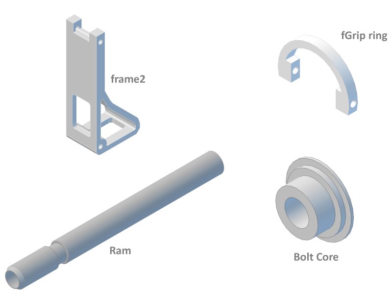
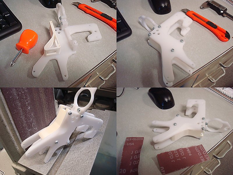
There are several parts that need to be machined and/or 3D printed. The drawings and STL files for each are included here.
Frame2: frame2.stl 3D printed, makes for a more comfortable Grip. Could otherwise be replaced with the part in the template set made out of 1/4" polycarbonate. fGrip Ring: fgrip.stl 3D printed, skips having to cross-drill a part that can be difficult to hold in a vice. Could otherwise be replaced with the part in the template set made out of 1/4" polycarbonate. Ramrod: ramrod.gif Has to be machined out of Aluminum, Delrin, or PVC. Which requires access to a machine lathe. Bolt Core: boltcore.gif Has to be machined out of Aluminum, or Delrin. Which requires access to a machine lathe. |
Step Two |
|
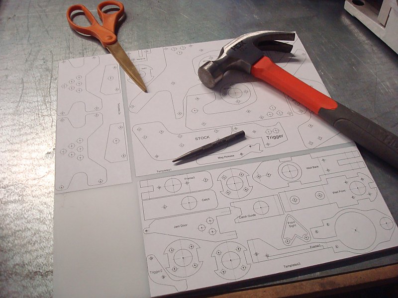
Download the cutting template sheets: caliburn_templates.doc Print them on full sheet label paper. The included legend will tell you how to lay out the templates to fill on a square foot of polycarbonate. It will also tell you what size holes need to be drilled and where. Using a Hammer and a Center Punch (or a Nail) put a centering divot on the centermark of every hole on every part template. |
Step Three |
|
Using a Drill Press and a #52 drill bit drill all the holes labeled "#52".
Using a Drill Press and a #36 drill bit drill all the holes labeled "#36". |
Step Four |
|
OPTIONAL STEP: Using a Drill Press and a #22 drill bit drill the center of the holes labeled "1/4". These holes are entirely decorative and non-functional. So decide now if you want to skip them.
Using a Drill Press and a #22 drill bit drill the center of the holes labeled "1/2" or larger. Using a Drill Press and a #22 drill bit drill the center of the holes labeled "#22". |
Step Five |
|
OPTIONAL STEP: Using a Drill Press and a 1/4 wood-boring drill bit drill the center of the holes labeled "1/4". These holes are entirely decorative and non-functional.
Using a Drill Press and a 9/16" Flat Wood-boring drill bit bore out all the holes labeled "9/16". Go slowly and carefully with minimal downforce to help avoid tearing the templates off the plastic. |
Step Six |
|
Using a Drill Press and a 9/16" Flat Wood-boring drill bit bore out all the holes labeled "9/16". Go slowly and carefully with minimal downforce to help avoid tearing the templates off the plastic.
Using a Drill Press and a 5/8" Flat Wood-boring drill bit bore out all the holes labeled "5/8". Go slowly and carefully with minimal downforce to help avoid tearing the templates off the plastic. |
Step Seven |
|
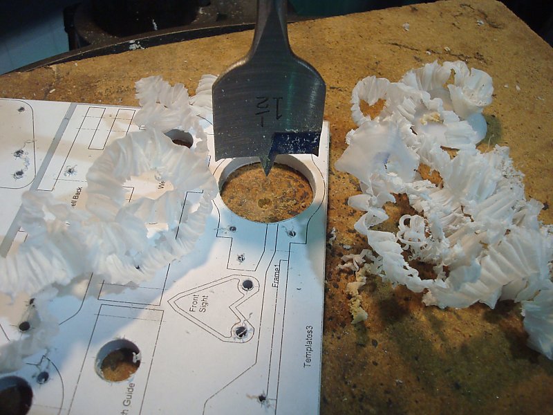
Set a piece of plywood on the table of the Drill Press so that you can drill through the sheet without hitting the table of the drill press.
Center drill over the only hole labeled "1-1/2" and clamp the plywood and polycarbonate to the table of the Drill Press Using the Drill Press and the 1-1/2" Flat Wood-boring drill bit bore out the hole labeled "1-1/2". Go slowly and carefully with minimal downforce to help avoid tearing the templates off the plastic. |
Step Eight |
| At this point it would be a good idea to peel the protective film off of the back of the sheet. Doing this after the parts are cut out can prove to be extremely time consuming. |
Step Nine |
|
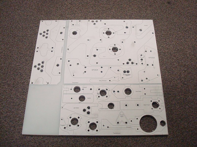
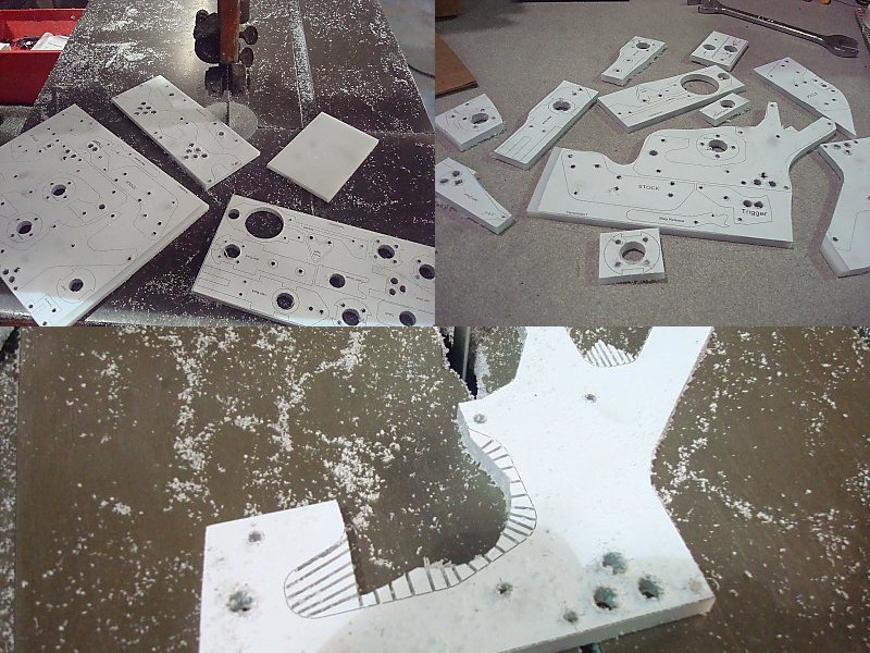
Using a Band Saw cut the sheet into quadrants based on the individual template sets. This will cutting apart the individual parts much easier.
Using a Band Saw coarsely cut all of the parts free from the plastic sheet. Add as many relief cuts as you think are needed for each part. A relief cut is a cut made perpendicular to the intended cutting line that allows excess material to break away as the cut is made along the intended contour. This allows a deeper blade to cut sharper corners than it would otherwise be able to. Using a Scroll Saw or a Band Saw accurately cut all of the parts to their outlines. |
Step Ten |
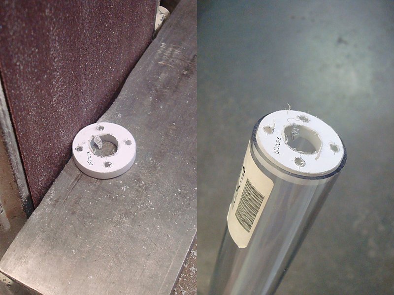
| Use a Belt Sander to sand down the round parts (bSupport, pCross) until they fit snugly inside your plunger tube and front tube materials. The Bolt1 part will need to be sanded down also, but will need to fit loosely inside your plunger tube material. |
Step Eleven |
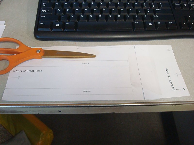
| Use Scissors to cut out the two halves of the Front Tube template. Tape them together as shown. |
Step Twelve |
|
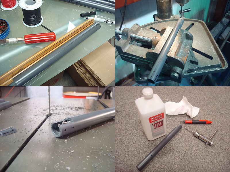
The length of this part has a somewhat wide tolerance, where-as the plunger tube does not. So if you intend to make the plunger tube and front tube out of the same length of tubing, make sure to cut the plunger tube FIRST.
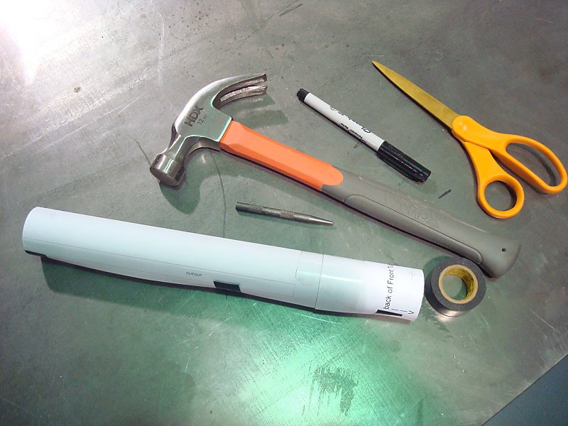
Use a Band Saw to cut a 12-inch length of the 1-1/2" tubing. Set this aside for later. Use the remainder of the 1-1/2" tubing for the Front tube. This piece can be anywhere from 12-1/8" to 11-1/2" in length. Use a Deburring Tool to clean the cut edges of both tubing lengths. Wrap the combined template around your front tube. Line the BACK of the template up with the end of the tubing, and tape it in place. Use a Hammer and a Center Punch to mark the holes centers. Also use it to mark the corners and several spots along the lines in the template for the slots and the window. Remove the templates and use a Tri-Sided Ruler and a Fine-Point Permanent Marker to connect the center marks that indicate where the slots and window are going to be cut. I also recommend marking the location of the centers so that it's easier to see where they are. |
Step Thirteen |
|
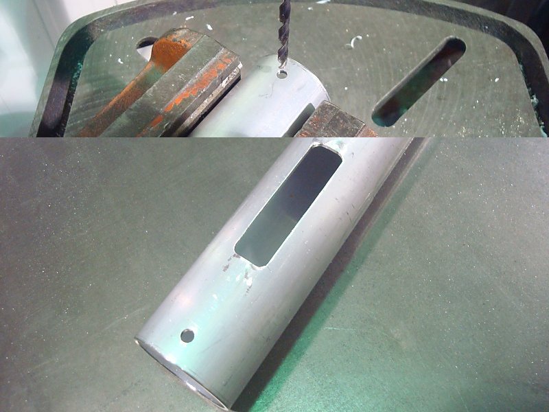
Use a Drill Press, Vice, and a #22 Drill Bit to drill all the holes that you previously marked.
Use a Rotary Tool with cutting discs or a Manual Knee Mill to cut out the window. |
Step Fourteen |
|
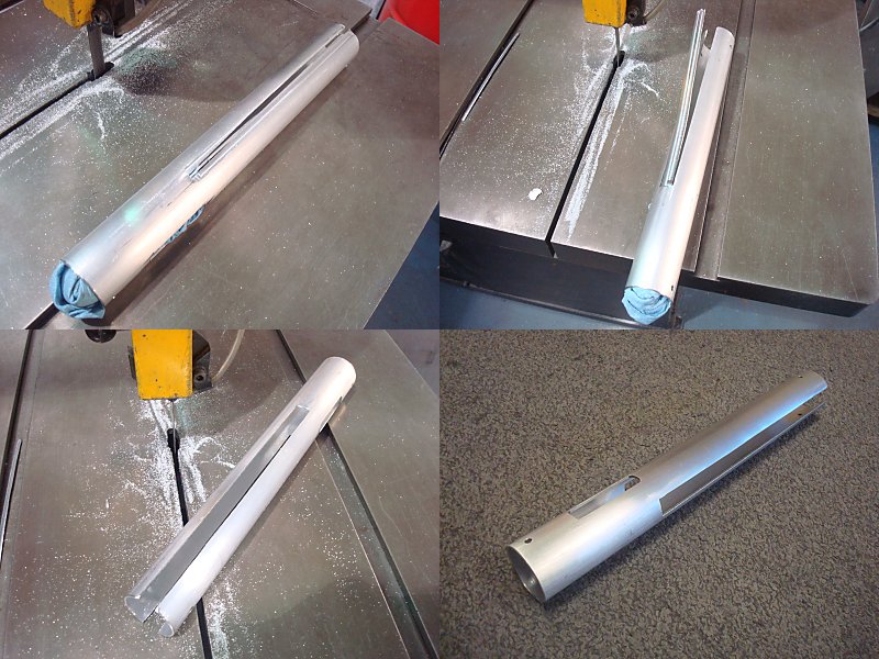
It's advisable to wear hearing protection during these steps anyways as the aluminum is going to be rather loud.
Stuff a shop rag into the back end of the Front Tube. Doing this prior to cutting will help reducing ringing and noise production. Line up the Front tube on the Band Saw so that the top side of the cut is going to be inside the line, and the bottom side of the cut is going to be cutting near the middle of the slot. Cut inside both lines for the top side slot but rotating the Front tube. You should be able to make both cuts while keeping the bottom side of the cut in the middle of the opposite slot that you will finish cutting later. One the two cuts are made, turn the Front tube on its side then bend up and cut away the "Peel" of aluminum. Repeat the process for the opposite side. Use many relief cuts to square off the end of both slots. Use a File and a Deburring Tool to clean of the cut edges of both slots. Use a Scotchbrite Pad to clean up the exterior surface of the finished part. Then clean and rinse it off with regular dish soap. |
Step Fifteen |
|
Use a Band Saw to cut a 9-3/8" long piece of SCH80 or SCH40 1/2 NPS PVC Pipe.
Using the dimensions provided from the Templates, use a -Sided Ruler and a Fine-Point Permanent Marker to scribe the hole spacing onto both sides of the Lower Stock Rod. Use a Hammer and a Center Punch to add centers to all of these marks. Use a Vice, Drill Press, and a #36 Drill bit to drill all 8 of the marked holes. Use a Band Saw to cut a slot out of the end with two closely-spaced holes as shown. This will act as clearance for the trigger linkage. Use a #6-32 Tapping bit and tapping wrench to add a thread to all 8 holes. You can use Rubbing Alcohol to remove all the permanent marker lines from the finished part. |
Step Sixteen |
|
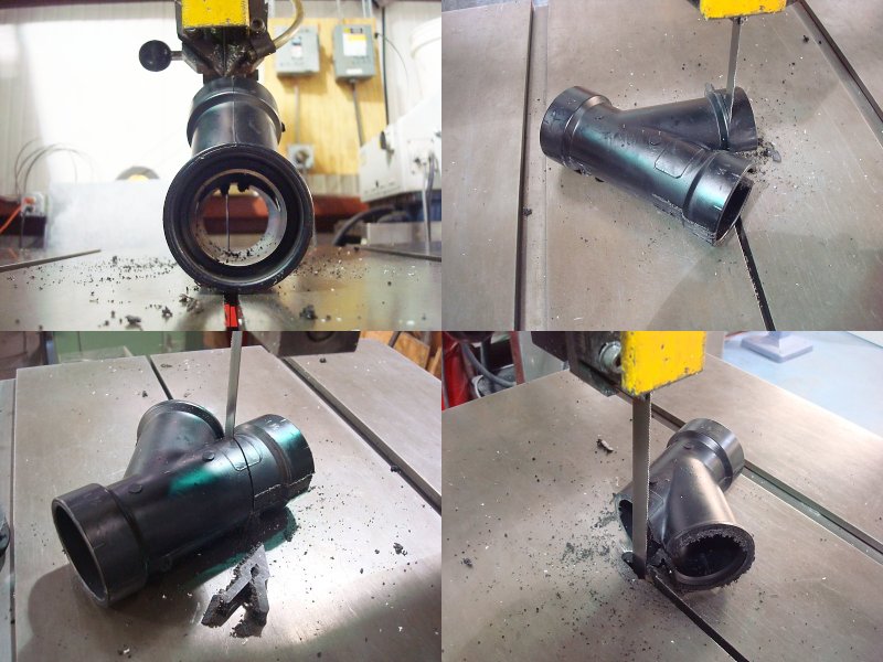
Stand the Wye Fitting up and use the Band Sawcut a 1/2" wide slot into the back of it as shown. You want to be able to completely remove the material in the "arm pit" of the wye and you'll end up cutting quite a ways into that one end in order to do so.
Cut the socket off the Branch end, but leave a little bit of the edge on. Cut from the "arm pit" to the flat side to completely remove that socket off of the wye fitting. Use a Deburring Tool to clean up all of the cut edges. It would also recommend using a File or Belt Sander to remove any nubs, bumps, or markings you don't want to leave on your finished Blaster. |
Step Seventeen |
|
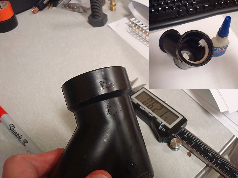
Use a Fine-Point Permanent Marker to mark the two holes you need to drill on opposite sides of the front end of the wye. These marks will be 5/8" away from the front end of the only uncut socket. You can use the molded lines as a guide for a Tri-Sided Ruler since they are placed exactly 45-degrees apart.
Use a Hammer and a Center Punch to add centers to both of these marks. Use a Drill Press and a #22 Drill Bit to drill both holes. Slide the fGrip Ring piece into the Wye and use two 5/8" length screws to line its holes up with the ones you just drill in the Wye. Use Super Glue to glue the fGrip Ring into the Wye. Remove the 5/8" length screws and set this part aside so that it can dry. |
Step Eighteen |
|
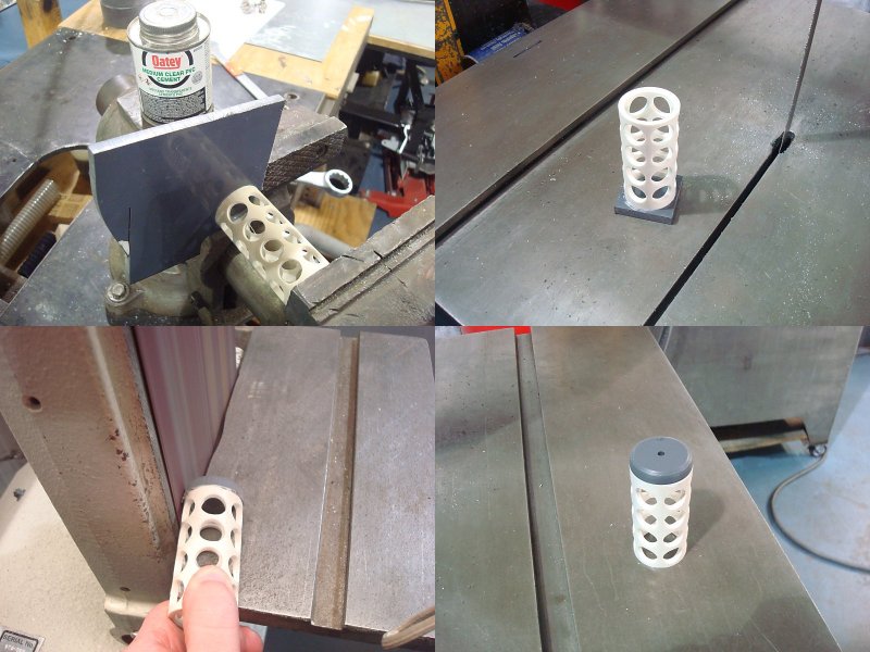
Use a Band Saw to cut a 2-3/4" long piece of 1 NPS PVC Pipe.
Use Scissors to cut out the "Wiffle Tube" template from the template set. Wrap this template around and tape it to the Pipe section. Use a Hammer and a Center Punch to add centers to all of these marks. Use a Drill Press, a Vice, and a 1/2" Wood-Boring Drill Bit to drill both holes. Use PVC Cement and a Vice to glue and clamp together the "Wiffle Tube" onto the corner of the grey CPVC sheet. Leave this to cure in the vice for 30 minutes Use a Band Saw to cut the combined parts off the grey CPVC sheet. Use a Belt Sander to sand the grey CPVC round to match the pipe OD. Use a Machine Lathe or a Drill Press with a #22 Drill Bit to drill a centered hole in the grey CPVC. |
Step Nineteen |
|
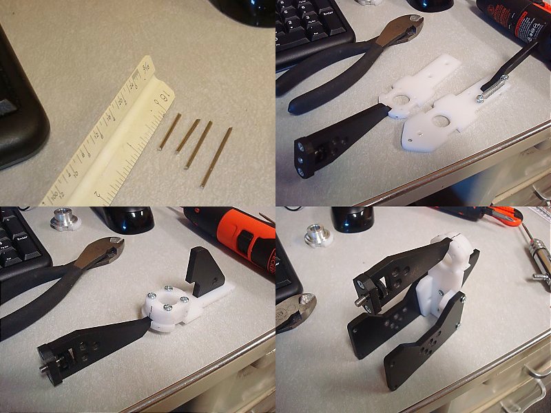
Make the Bolt Arm parts to the dimensions specified in the Template Set. ENSURE THAT THESE TWO PARTS ARE MADE IDENTICAL OR THEY WILL NOT WORK PROPERLY. Drill and countersink one hole in each, and drill and tap the other hole in each. Then sand or file down the cut edges. Make the Trigger link part to the dimensions specified in the Template Set. Drill both holes to #22. Then sand or file down the cut edges. This piece can alternatively be made out of 1/16" OD weld rod if the bends are added to it at the same spacing as the drill holes. Use a Band Sawto cut two 2-1/2" length of 5/8" OD aluminum tube. Fully countersink the inside edge of one end for each. The shallower this angle is the better. |
Step Twenty |
|
Use the 3/4" OD 82 Degree Countersink and a Drill Press to countersink of side of the 9/16" hole in the Catch Plate piece.
Use a #6-32 Tapping Bit and Tapping Wrench to add a thread to the other drilled hole. Remove the templates and protective film. Then deburr all of the cut edges of this part using a Hobby Knife or Deburring Tool. |
Step Twenty One |
|
Now that all of your parts are cut to shape, it's time to add the remaining features to each.
Holes labeled for a certain size that include a larger outline need to be countersunk. Use the 3/4" OD 82 Degree Countersink and a Drill Press to countersink these holes. Use a Fine-Point Permanent Marker to scribe on the edges of the sheets that include hole centers indicators on the edges of the parts shown. Remove the Protective film from these parts, then deburr all of their cut edges with a Hobby Knife or Deburring Tool. Use a Drill Press, Vice, and #51 Drill Bit to drill the center of the edges of these parts at every scribed line that indicates a #51 hole. Use a Drill Press, Vice, and #36 Drill Bit to drill the center of the edges of these parts at every scribed line that indicates a #36 hole. Drill these no more than 3/4" deep and make sure to peck drill. Peck drilling is drilling a little, then backing out to clear chips, then drilling a bit deeper, and backing out again. If needed, lubricate the drill bit with dish soap. Use a #6-32 Tapping Bit and Tapping Wrench to add a thread to all the #36 holes in these parts. |
Step Twenty Two |
|
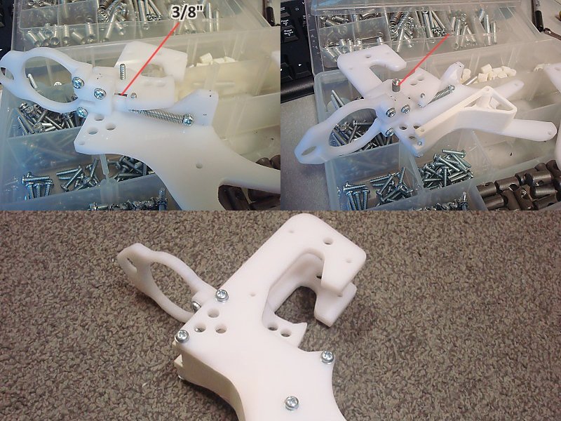
Once the Magwell Front part has all of its cross-drilled holes added, the top side of it can be sanded or cut down to the final rounded shape. The narrow end of it and the Magwell Back parts can have a beveled or filleted edge added to them.
Put a Thumbscrew into the JamDoor2 piece from the opposite side of the countersinks. Then attach it to the JamDoor1 piece using two 3/8" length flat head screws. If previously missed, use a Band Saw to cut the angled slot in Frame 1 that leads into the 1-1/2" hole. Attach the Frame1a piece to the Frame1 using three 1/2" length screws. Making sure that the slots on both parts line up. |
Step Twenty Three |
|
Use a #6-32 Tapping Bit and Tapping Wrench to add a thread to all the #36 holes in the Frame2 Part (whether cut from polycarbonate or 3D-printed).
Do a test assembly of the Grip Sides, Frame1, and Frame2 parts as shown using 1/2" length screws. The slot in Frame1 should be to the left side of the assembly. Use a Belt Sander to add relief scoops for your hand in the Grip Sides at the back of the grip. I find it easiest to use the top of the belt where it curves over the upper pulley. Do this as much as you'd like until the grip fits your hand well. Be careful to not burn your hand on the screw heads as they will get hot from intermittent contact with the sanding belt. Use a Half-Round Rasp or Needle File to touch up any shape edges or corners you couldn't reach with the Belt Sander. Use a sheet of 300 grit Sandpaper to soften all the edges and reduce the texture of the areas you just hit with the belt sander. Replace all of the 1/2" length screws you damages in the sanding process. |
Step Twenty Four |
|
Screw a 1-1/4" length screw in all of the way from the left Grip Side plate. Slide a 3/8" length spacer onto it.
Use two 1/2" length screws to attach a spring from the left side of the Trigger to the backside of the Frame1 assembly. Slide the spring-attached Trigger onto the 1-1/4" length screw. Slide a quantity of Five or Six #6 washers onto the 1-1/4" screw so that when the right Grip Side plate is attached the Trigger is held squarely, but doesn't resist pivoting. Attach the right Grip Side plate with 1/2" length screws. |
Step Twenty Five |
|
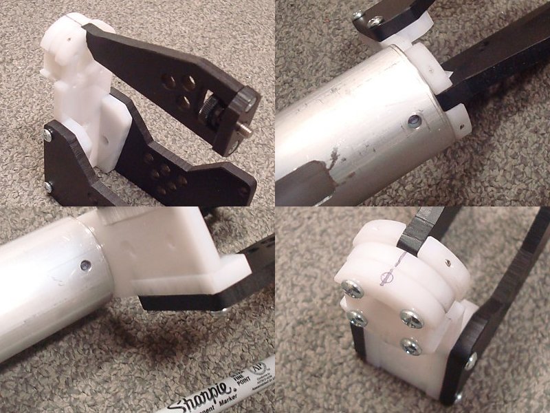
Use Six 1/2" length screws to attach the Catch Guide, Frame3, and Lower Stock Rod parts to the Right Stock Side plate.
Use two 1/2" length screws to attach a spring from the Right Stock Side plate to the Catch Plate. Screw a 1-1/4" length screw in all of the way from the Right Stock Side plate. Slide a quantity of Five or Six #6 washers onto the 1-1/4" screw. Slide the Trigger2 piece onto the 1-1/4" length screw. Slide a 3/8" length spacer onto it next. Then attach the Left Stock Side Plate onto the assembly using 1/2" length screws. Use a Hammer to lightly tap both of the pCross parts onto the non-chamfered end of one of the 2-1/2" long 5/8" OD Aluminum tubes. Do this until the end of the tube is flush with the back of the second pCross piece. Attach the pCross assembly to the Stock assembly using two 5/8" length screws. |
Step Twenty Six |
|
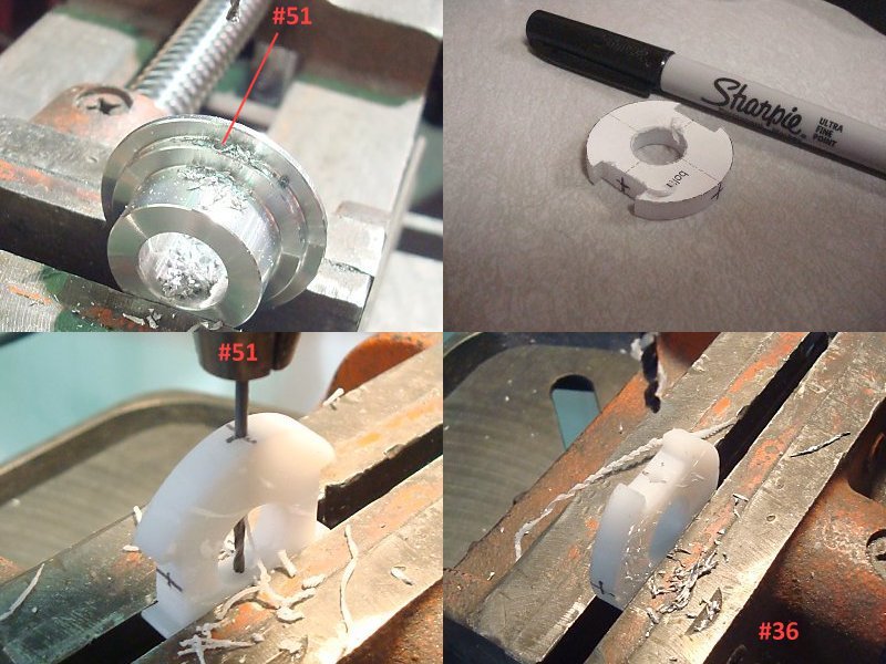
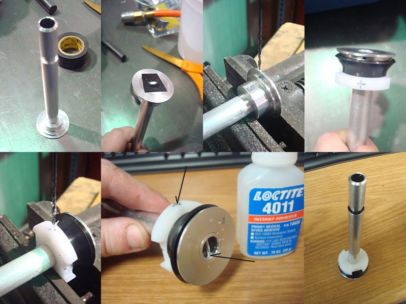
Use a Drill Press, Vice, and #51 Drill Bit to drill into the 1-1/8" OD edge of the Bolt Core piece. You need to peck drill all the way through this part and out the other side.
Use a Fine-Point Permanent Marker to scribe on the edges of the Bolt1 part that include hole centers indicators on the edges. Use a Drill Press, Vice, and #51 Drill Bit to drill into the edge of the Bolt1 piece at the top of the rounded sides. You need to peck drill all the way through this part and out the other side. Use a Drill Press, Vice, and #36 Drill Bit to drill into the edge of the Bolt1 piece at the bottom of the square cutouts. You need to peck drill all the way through into the center of the part, then flip it over and drill from the opposite side. Use a #6-32 Tapping bit and tapping wrench to add a thread to those two holes. |
Step Twenty Seven |
|
Use a Ruler and Wire Cutters to cut 4 pieces of 1/16" OD Weld Rod (or a similar guage size of finishing nails). The lengths you need are: 3/4", 3/4", 1", and 1-1/4"
One of the 3/4" length is used to retain the Jam Door assembly into the top of the Mag Well Front piece. The flat side of the Jam Door should hinge towards the side with countersunk holes. And the other 3/4" length is used to attach the Mag Release to the Mag Well Back piece. The mag release lever side should stick out opposite of the side with countersunk holes. Use two 1/2" length screws to attach a spring from the Mag Well Back Piece to the Mag Release. Use four 5/8" length screws to attach two bSupport pieces to the front side of the Mag Well Front part. Use two 3/8" length flat head screws to attach the Gusset to the front side of the Mag Well Front part. Use four 5/8" length screws to attach the Mag Well Cheek and Side plates to the narrow sides of the Mag Well Front part. |
Step Twenty Eight |
|
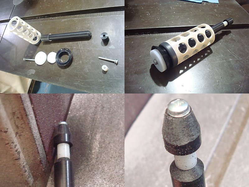
Slide the RamRod Part into the center of the BoltCore part as shown.
Use Electrical tape on the backside of the two parts to keep them from shifting around in the next few steps. Use a Drill Press, Vice, and #51 Drill Bit to drill into the 1-1/8" OD edge of the BoltCore piece where you previously drilled. You need to peck drill all the way through the RamRod and out the other side. Remove the Electrical tape and take the pieces apart. Reassemble them with the Bolt1 piece and the Skirt Seal slid onto the BoltCore part. Line up the holes you just drilled. Insert the 1" length piece of weld rod you previously cut into this hole until it's fed though both sides of the RamRod. Use a Drill Press, Vice, and #51 Drill Bit to drill into the edge of the Bolt1 piece where you previously drilled. You need to peck drill all the way through the RamRod and out the other side. Insert the 1-1/4" length piece of weld rod you previously cut into this hole until it's fed though both sides of the RamRod. Use Super Glue to retain these piece of weld rod (so that they don't fall out under vibration. The BoltCore piece can be glued from inside of the RamRod. The Bolt1 piece can be glued in the ends of both holes. |
Step Twenty Nine |
|
If it did not already get scribed, mark the centerline on the top of the bSupport parts using a Fine-Point Permanent Marker.
Remove the Gusset from the Mag Well Front assembly and slide the Front Tube onto the bSupports. Line up the top hole in the Front Tube with the line you just scribed on the bSupport parts. Use a Fine-Point Permanent Marker to trace the inside of both holes in the Front Tube. Remove the Front Tube, then remove the bSupports from the assembly, then use a Drill Press and a #36 Drill bit to drill both of the marks made in the edge of the forward most bSupport piece. Use a #6-32 Tapping bit and tapping wrench to add a thread to those two holes. Reattach the bSupport parts to the Mag Well Front Assembly. |
Step Thirty |
|
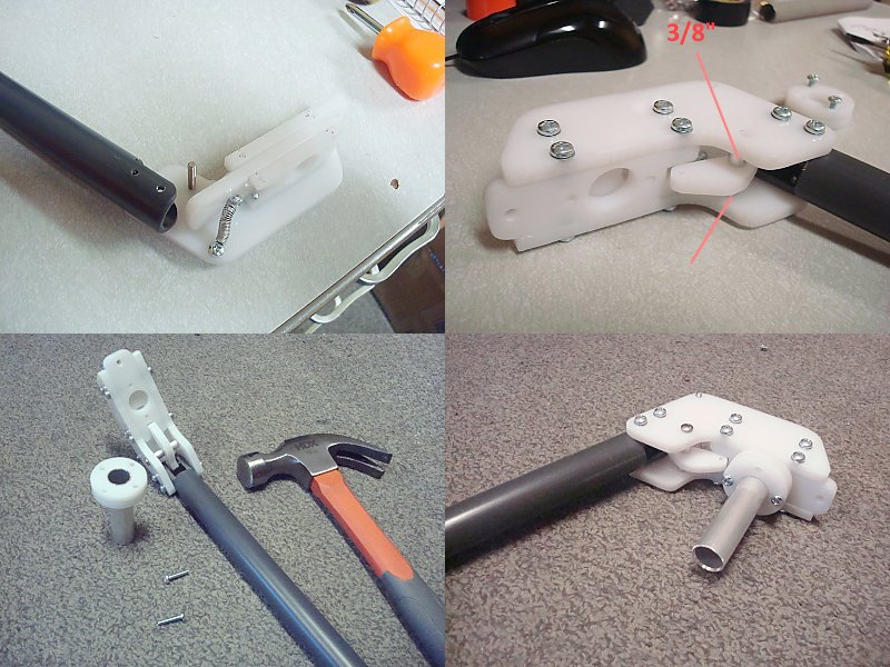
Loosen the 5/8" length screws and use a Hammer to tap the Mag Well Front assembly onto the chamfered end of the remaining 5/8" OD Aluminum tube section. Do this until the chamfered end is flush with the back side of the Mag Well Front piece.
Retighten the 5/8" length screws. |
Step Thirty One |
|
Use a Band Saw to cut a 10-inch length piece of the 5/8" OD 1/2" ID PETG tubing.
Use the 3/4" OD 82 degree countersink to chamfer the inside of both ends. Check the fit of the Bolt Arm pieces in the square cutouts in the sides of the Mag Well Front and Mag Well Back parts/assemblies. These need to fit somewhat loosely, if they do not, use a File or Half-Round Rasp to widen out or soften their edges until the Bolt Arm parts can slide freely in them. |
Step Thirty Two |
|
Slide the remaining bSupport piece into the slot end of the Front Tube. Line one of its centerline marks up with one of the holes. Use a Fine-Point Permanent Marker to trace the inside of both holes onto the bSupport. It be easier to trace these holes if the Front Tube has a rubber band double-up around it so that it holds the bSupport more securely.
Use a Drill Press and a #36 Drill bit to drill both of the marks made in the edge of the bSupport piece. Use a #6-32 Tapping bit and tapping wrench to add a thread to those two holes. Attach the bSupport and Front Sight pieces together using four 1/2" length screws and two 3/4" length standoffs. If desired, paint this set of parts with Fluorescent Orange Spray Paint. Set it aside to dry for 30 minutes. Slide the Foregrip Wye into the slots of the Front Tube. Attach the Front Sight assembly into the end of the Front Tube using two 1/2" length screws. |
Step Thirty Three |
|
To make the Chamber Coupler use a Band Saw to cut a 2-inch long piece of 1/2 NPS Clear PVC Pipe. Or alternatively a 5/8" ID piece of Polyester or Polycarbonate tubing.
If the ID of this section of tubing is smaller than 5/8", use a Machine Lathe and a 5/8" Wood-Boring Drill Bit to bore it out. Use a Hammer to tap this clear section to tubing onto the front 1/2" of the 5/8" OD aluminum tube that is sticking out the end of the Mag Well Front Assembly. Slide the Front Tube Assembly onto the Mag Well Front Assembly and line up the holes in both. Attach them together with two 1/2" length screws. Reattach the Gusset part using two 3/8" length flat head screws. Slide the 10-inch length barrel in through the Front Sight Assembly, and back through the Front Tube until it reaches the clear Chamber Coupler. It should then be slid into the Chamber Coupler 1/2" at minimum. |
Step Thirty Four |
|
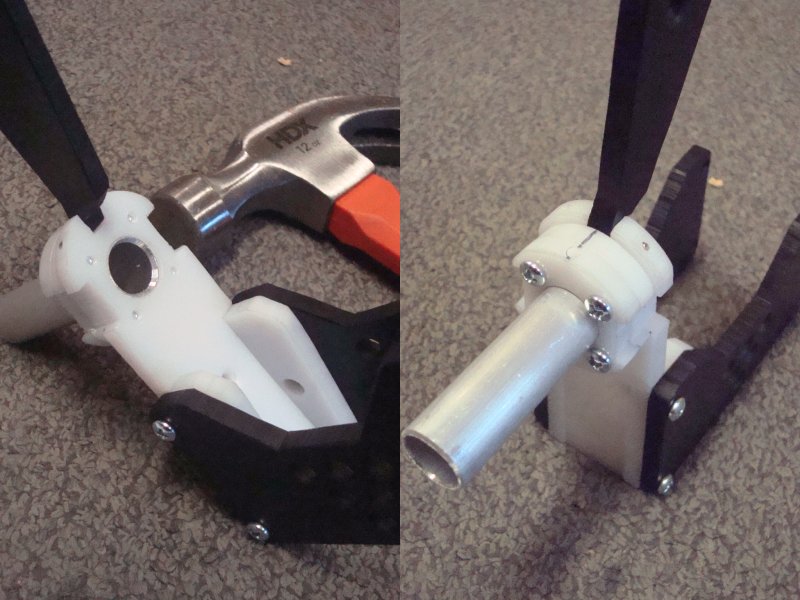
Attach the Bolt Arm plates into the square cutouts in the side of the Bolt 1 piece using two 3/8" length flat head screws.
Add a rubber pad to the face of the Bolt assembly. I'm using adhesive-backed silicone that was cut from a sheet using die-cutting punches. Slide the Bolt Assembly into the back of the Mag Well Front assembly. Attach the Bolt Arms to the Foregrip Wye using two 5/8" length Screws. |
Step Thirty Five |
|
Use a Band Saw to cut a 4-3/8" long piece of 1/2" OD Black Delrin Rod.
Use a Machine Lathe or Drill Press with a #36 Drill Bit to drill a 1" deep hole into both ends. Use a #6-32 Tapping bit and tapping wrench to add a thread to those two holes as deep as you can manage. To make this easier coat the tapping bit in regular Dish Soap. Use a Band Saw to cut a 1/2" to 3/4" length piece of 1/2" OD Black Delrin. Use a Machine Lathe or Drill Press with a #22 Drill Bit to drill all the way through the center of it. Assemble the Plunger Rod as shown using two 1-1/4" length screws and a 3/8" length spacer. Use a Belt Sander to taper the end of the short Black Delrin spacer you made earlier. Make it come to a point as narrow as the screw that holds it in place. |
Step Thirty Six |
|
Use a Band Saw to cut a 12" long piece of 1/2" OD Black Delrin Rod.
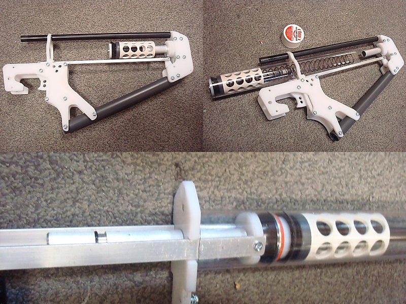
Use a Machine Lathe or Drill Press with a #36 Drill Bit to drill a 1" deep hole into both ends. Use a #6-32 Tapping bit and tapping wrench to add a thread to those two holes as deep as you can manage. To make this easier coat the tapping bit in regular Dish Soap. Slide this long rod through the hole in the top of Frame2. Attach it to the top hole of the stock assembly with a 1/2" length screw. Attach the end of the Lower Stock Rod to the Grip Assembly using four 1/2" length screws. Attach the Trigger Link to Trigger1 and Trigger 2 using 3/8" length screws. The catch plate may need to be held up in its open position for this to be done correctly. I would also recommend adding thread-locking compound to these screws before screwing them in. Also: Do not overtighten these screws. The Trigger Link still needs to be able to pivot on them without binding. Check the function of the Plunger Assembly in th catch. Remove the Plunger Assembly. Coat the inside of one end of the Plunger Tube with Silicone Grease, then push the Plunger head first into the Plunger Tube from this same end. Add the K26 or K25 spring. Slide the Plunger tube spring-end first into the 1-1/2" hole of the Finished Grip/Stock Assembly until it is seated over the pCross parts. Slide the Mag Well Back part onto the RamRod after angling inbetween the Bolt Arms Slide the Bolt Assembly into the end of the Plunger Tube to add some lubrication to it. |
Step Thirty Seven |
|
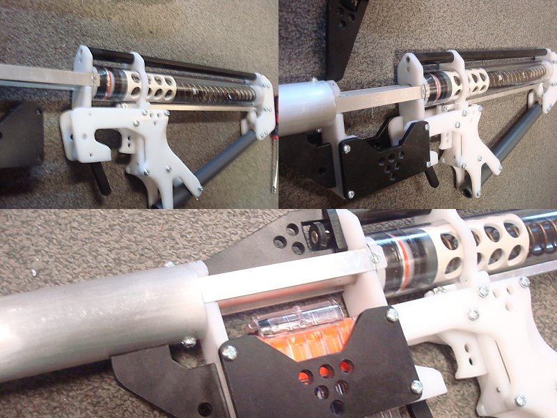
Partly attach the top of the Mag Well Back piece to the end of the Upper Stock Rod using a 3/8" length flat head screws. Do not tighten this screw all the way.
Slide the Mag Well Sides over the Grip Side panels, then line the Mag Well Back piece up with any of these holes. Partly attach all three together with four 5/8" length screws. Slide a Magazine into the Mag Well until it latches. If it does not latch you may need to disasseble the blaster and file down the top side of the tooth on the Mag Release. Once the Magazine is seated over the RamRod, tighten all five screws. Hinge the Jam Door closed and tighten its thumbscrew. |
Step Thirty Eight |
|
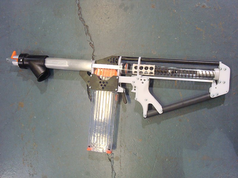
Cycle the Plunger and dry fire a half dozen times making sure to plug the barrel with your finger tip when you do.
YOU ARE NOW FINISHED Accuracy with full-length darts can be pretty bad at full power. If you intend to use this blaster with them I would recommend removing the O-Ring from the RamRod. Otherwise I would suggest using the O-Ring with shorter darts (1-1/2" to 1-1/4" in overall length) in Artifact mags as that will offer you better distance and accuracy. |